Safety engineering
Basic Safety − STO
Technical data
10
l
136
EDS700ACBA EN 5.1
10.6.2 Technical data
Supply
The inputs are isolated and designed for a low−voltage supply through a safely separated
power supply unit (SELV/PELV) of 24 V DC. P/N switching input signals and test pulses
£ 1 ms are permissible.
Active sensors are directly wired to the X1 terminal strip.
Passive sensors are wired to the X1 terminal strip via a switching device. The switching
device must comply with the required control category of the application.
There is no monitoring for short circuits.
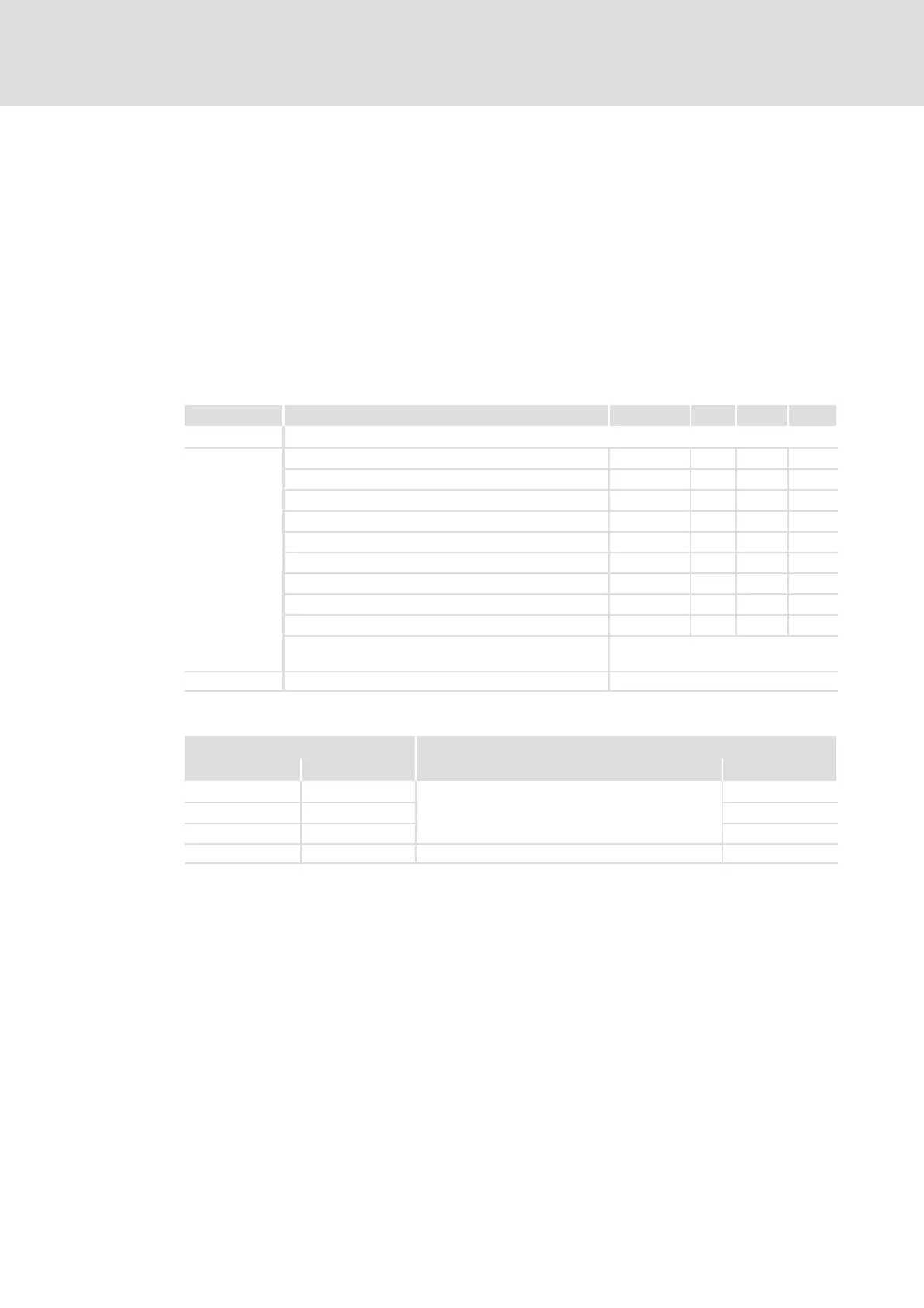
Terminal X1 Specification [Unit] min. typ. max.
The input channels comply with the IEC 61131−2 standard, type 1.
SIA, SIB
Low signal
V −3 0 5
High signal
V 15 24 30
Input capacitance at switch−off
nF 3
Input delay (tolerated test pulse)
ms 1
Switch−off time
ms 5
Running time
ms 1
Input current mA 2 15
Input capacitance at switch−on
nF 100
Test pulses permissible at intervals of ms 10
Polarity reversal protection When polarity is reversed: no function
and no destruction.
GS Ground for SIA/SIB
Truth table
Safe input / channel Controller
SIA SIB Description of device status Enable
00
"Safe torque off" activated
0
0 1 0
1 0 0
1 1 Drive active 1
 Loading...


