DC−bus operation
Braking operation in a drive system
Basic considerations
7
l 121
EDS700ACBA EN 5.1
7.6 Braking operation in a drive system
7.6.1 Basic considerations
If the regenerative power of a drive exceeds the storage capacity of the DC bus, the
excessive energy must be consumed or dissipated. Target of the DC bus is to use the
excessive energy for other axes.
Check for all operating situations that may occur in the DC−bus interconnetion whether the
brake power provided by the brake choppers is high enough for the maximum regenerative
power that may occur. If necessary, several power supply modules with an integrated brake
chopper can be integrated into the drive system to increase the brake power (parallel
connection).
If several brake choppers are used, the following conditions must be met:
ƒ The limiting monitoring functionalities must be considered when dimensioning the
continuous brake power for the DC bus:
– Brake chopper monitoring
– Brake resistor monitoring
ƒ The temperature monitoring of the brake resistors must lead to power−off, otherwise
the brake resistors or devices may be destroyed.
ƒ The brake choppers are protected by changing the duty cycle or switching them off
temporarily. They are automatically switched on again.
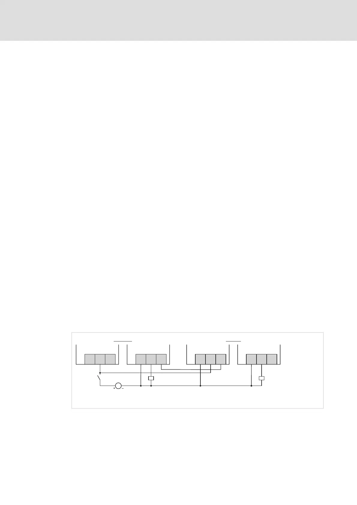
ƒ One device must be defined as "master", and the other devices must be defined as
"slaves", in order to provide for the simultaneous switching of all brake choppers,
irrespective of tolerances. How to proceed:
– For "Slave activation", apply digital input DI3 of each slave to GND potential
(GD/0 V). By this, the device−internal brake chopper switching threshold of the
slave is set to a value above the tolerance zone (790 V).
– For control by the master, interconnect digital output DO1 of the master with DI1
of the slaves. Like this, the slaves will chop on request by the master, isochronously
with the master (at 765 V).
X20.2
DO1
DO2
GD
X20.1
DI1
DI2
DI3
Master
Slave
|
X20.2
DO1
DO2
GD
X20.1
DI1
DI2
DI3
DC 24 V
(+19.2...+28.8 V)
i700S010 3
Fig. 13 Wiring of X20
X20 Connection of digital inputs and outputs at the power supply module
.1 Connector on the left−hand side
.2 Connector on the right−hand side
DIx Digital input
DOx Digital output (e.g. for controlling relays)
GD Reference potential GND