6. Hydraulic System
NOTE: Hydraulic system installation is NOT covered in
this publication.
Lewmar hydraulic windlasses have been designed for
ease of installation and follow a straightforward hydraulic
and mechanical installation procedure.
Windlass unit should be connected to a hydraulic
powerpack with directional control valve installed to
control the windlass movement.
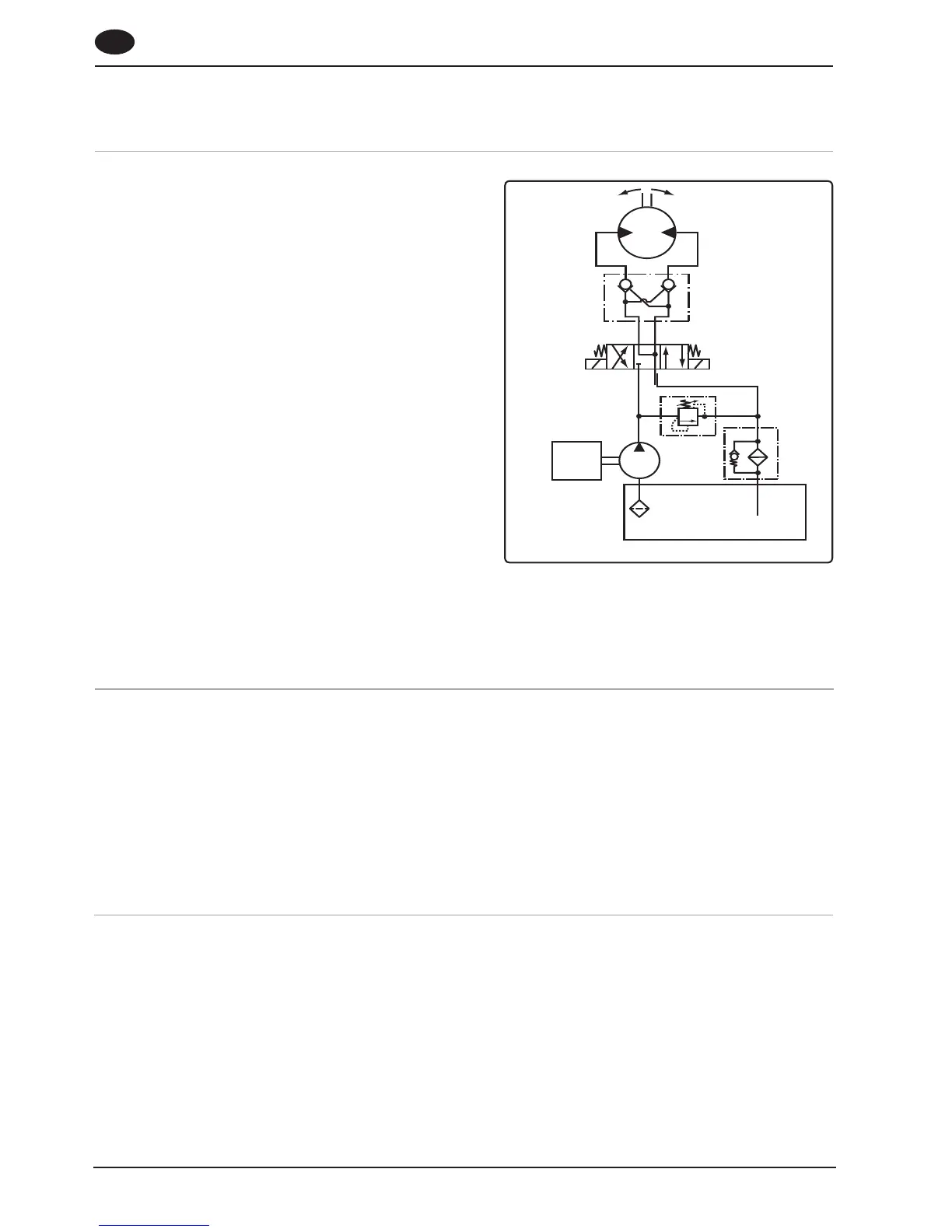
Fig 6.1 shows a typical hydraulic circuit for a V6 windlass.
The purpose of this manual is to provide the reader
with sufficient information to install and operate a
hydraulic windlass. It assumes the reader will be familiar
with sailing craft, marine hydraulics and mechanical
installation and safety requirements. If in any doubt
consult a qualified marine engineer.
The installation of hydraulic systems requires a high level
of cleanliness. The ingress of dirt will dangerously impair
the safe operation of the system and cause premature
wear of hydraulic components.
The hydraulic motor/gearbox consists of a high torque hydraulic motor fitted to a 7:1 90 degree gearbox.
The hydraulic motors have a maximum pressure rating of 180 bar and can be used with an oil supply of up to 57 l/
min.
The motor gearboxes are not self sustaining. A dual Pilot Operated Check Valve (POCV) must be installed in
the system to temporarily sustain any load. The POCV can be line mounted (as shown in Fig 6.1-1) or modular
type if for example a CETOP 3 directional valve is being used.
NOTE: To permanently sustain a load a Chain Stopper must be used.
6.2 Hydraulic motor/gearbox
1. For reliable operation and safety it is essential to use reinforced braid hose for connecting to the motor A and
B ports which conforms to SAE100R2A or DIN 20 021 Part 2.
2. The recommended hose sizes are:
Up to 30 l/min + 1/2” (13 mm) bore diameter.
Up to 40 l/min + 5/8” (16 mm) bore diameter.
Up to 57 l/min + 3/4” (19 mm) bore diameter.
Ref: 3.78 litres = 1 US gallon
4.54 litres = 1 Imperial gallon
6.3 Hose types
6.1 Installation
 Loading...