16
Installation
- To avoid picture noise (interference), leave an adequate distance between the VCR and TV.
- Typically a frozen still picture from a VCR. If the 4:3 picture format is used; the fixed images on the sides
of the screen may remain visible on the screen.
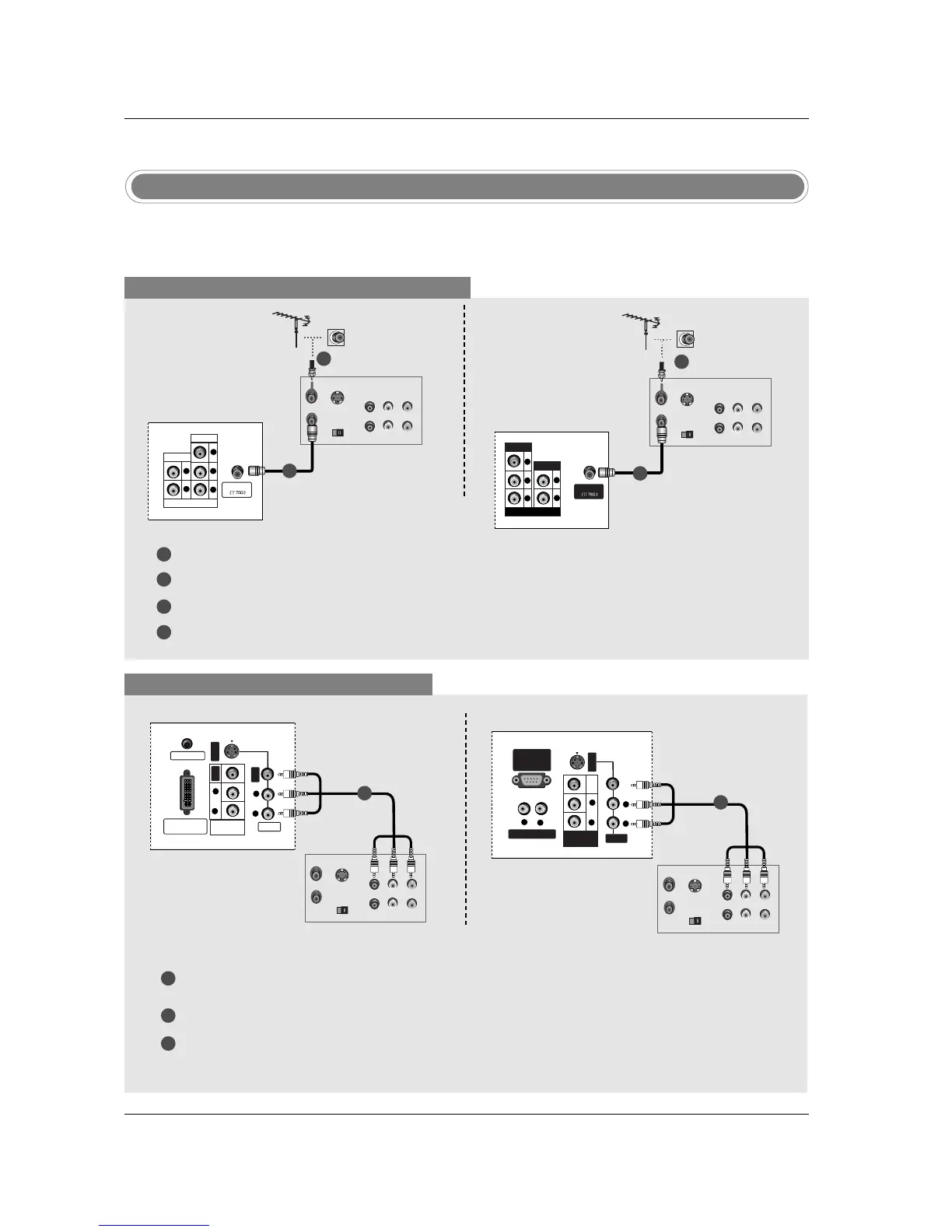
VCR Setup
NOTE: All cables shown are not included with the TV.
When connecting with an antenna cable
1
2
3
4
Antenna
PR
PB
Y
R
L
VIDEO
COMPONENT 1
AUDIO
S-VIDEO
OUT
IN
(R) AUDIO (L) VIDEO
34
OUTPUT
SWITCH
ANT OUT
ANT IN
Connect the RF antenna out socket of the VCR to the Antenna socket on the set.
Connect the antenna cable to the RF antenna in socket of the VCR.
Set VCR output switch to 3 or 4 and then tune TV to the same channel number.
Insert a video tape into the VCR and press PLAY on the VCR. (Refer to the VCR owner’s manual.)
1
2
TV Back panel (32inch)
VCR
When connecting with a RCA cable
PC SOUND
DVI INPUT
(PC/DTV INPUT)
S-VIDEO
VIDEO
AUDIO
R
L
VIDEO
VIDEO
AUDIO
R
L
MONITOR
OUT
S-VIDEO
OUT
IN
(R) AUDIO (L) VIDEO
34
OUTPUT
SWITCH
ANT OUT
ANT IN
VCR
1
1
2
3
Connect the AUDIO/VIDEO jacks between TV and VCR. Match the jack colors (Video = yellow, Audio
Left = white, and Audio Right = red)
Insert a video tape into the VCR and press PLAY on the VCR. (Refer to the VCR owner’s manual.)
Select Video input source with using the INPUT button on the remote control.
VIDEO
VARIABLE AUDIO OUT
RS-232C INPUT
(CONTROL
/SERVICE PORT)
S-VIDEO
AUDIO
VIDEO
VIDEO
R
R
L
AUDIO
R
L
L
MONITOR
OUT
S-VIDEO
OUT
IN
(R) AUDIO (L) VIDEO
34
OUTPUT
SWITCH
ANT OUT
ANT IN
VCR
TV Back panel (32inch)
TV Back panel (26inch)
1
S-VIDEO
OUT
IN
(R) AUDIO (L) VIDEO
34
OUTPUT
SWITCH
ANT OUT
ANT IN
Antenna
R
PR PB Y
L
VIDEO
COMPONENT 1
AUDIO
TV Back panel (26inch)
VCR
2
1
 Loading...