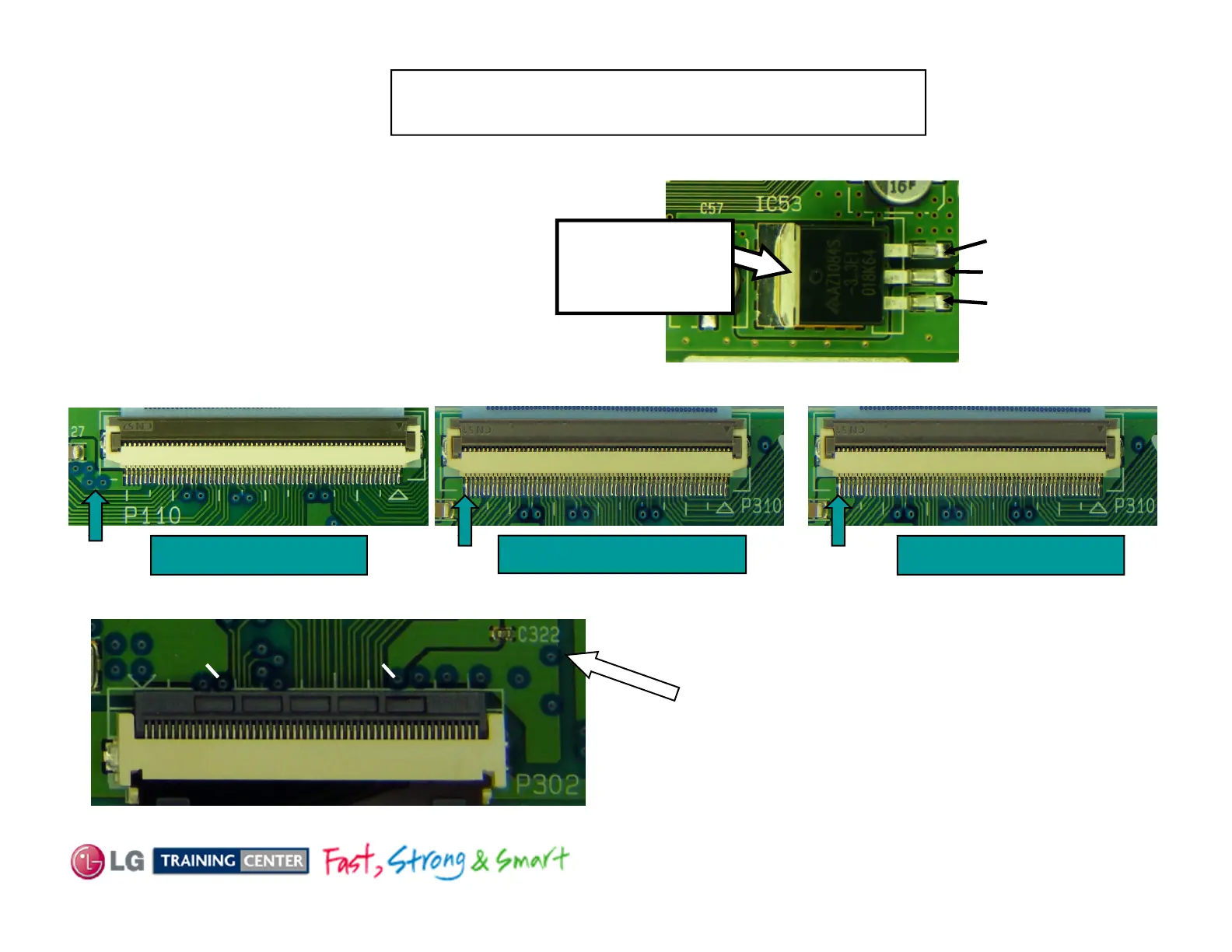
TCP 3.3V B+ CheckTCP 3.3V B+ Check
Warning: DO NOT attempt to run the set with the
Heat Sink over the TCPs removed.
Checking IC53 for 3.3V, use center pin or Top of component.
For Connectors P101, P102
and P104 on the Control
IC53
4.98V
3.3V
,
section. 3.3V leaves on Pins
1~4 of all three connectors.
3.3V for TCPs
IC53 on
With all connectors connected, place the
Red Lead On 3.3V Diode Check (0.62V)
Bl k L d O 3 3V Di d Ch k (0 33V)
n
3.3V in on Pins 57 ~ 60 on any connector from the Control board
ac
ea
n
.
o
e
ec
.
This also test Data ICs on X-Boards
Left X Board P110 Right X Board P310
Center X Board P310
All Connectors to All TCPs look very similar for
the 3.3V test point. The trace at pins 14 and 38 of
3.3V 3.3V
3.3V
each connector. There will a small feed trough
off pin 14 and 38 you can use for Test Points.
Example here from P302. You can also note a
Capacitor (C322 here) left side to identify Pin 38.
You can only check for continuity back to IC53,
you can not run the set with heat sink
.
.
May 2011 50PV450 Plasma
12 4
,
unless you disconnect VA from the Y-SUS to the
Left X-Board.
 Loading...