3. Product Overview DVIDL-OPT series – User's Manual 10
Electrical Connections
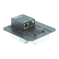
DC 5V Connection
The device has locking DC connector to establish robust and safe
power connection. After plugging it in, turn the plug clockwise as you
can see in the picture below.
Locking DC connector
Do not forget to turn the connector counterclockwise before trying to
disconnect the power adaptor.
WARNING! Always use the supplied 5V power adaptor or
Lightware's rack mountable power supply units. Warranty is void if
damage occurs due to use of a different power source.
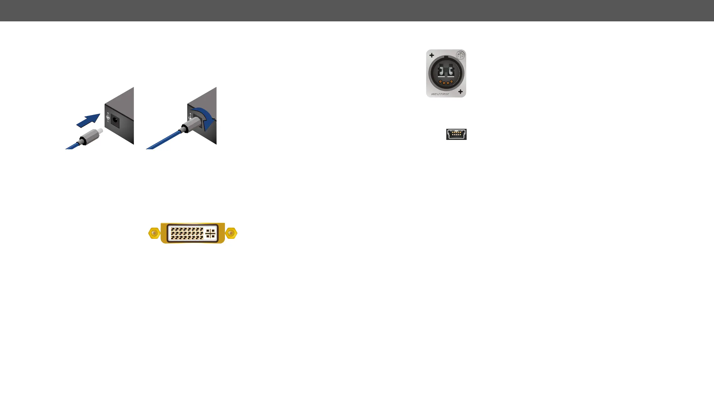
DVI Inputs and Outputs
only” DVI-I Dual-Link connectors
(only digital pins are internally connected). This way, users can plug in
any DVI connector, but keep in mind that analog signals (such as VGA
or RGBHV) are not processed.
Always use high quality DVI cable for connecting sources and displays.
Pay attention to the DVI cable, if dual-link signal is to be sent, use only
dual-link DVI cables.
As a special feature, the device is able to supply 500 mA current on
optical DVI transmitters. Standard DVI outputs or VGA cards supply
optical cable.
12V 1.5A DC
5V 1.5A DC
PIN: 2.35mm
PIN: 2.35mm
link video signal is sent, only one channel is used
(from “channel A” on transmitter to “channel B”
channels are used for signal transmitting.
found in the Maximum Fiber Cable Extensions section.
USB Connector
The DVIDL-OPT series extenders provide standard USB mini
purposes.
AB
 Loading...