EasyManua.ls Logo

Lightware HDMI-3D-OPT-TX210A User Manual

Lightware HDMI-3D-OPT-TX210A
106 pages
To Next Page IconTo Next Page
To Previous Page IconTo Previous Page
Page #24 background imageLoading...
Page #24 background image
The System controller can send RS-232 messages to the transmitter by using LW3
protocol methods, see settings in section 8.7.7 on page 82.
The Transmitter can send RS-232 messages to the HDTV or the Extender by using LW3
protocol methods; in section 8.7.7 on page 82.
4.3.1. Serial interface
Technical background
Serial data communication can be established via the local RS-232 port (Phoenix connector)
or via the optical line. The RS-232 ports – which are connected to the microcontroller – can
be congured separately (e.g. if the Baud rates are different, the microcontroller does the
conversion automatically between the ports). The RS-232 port can be switched to Control
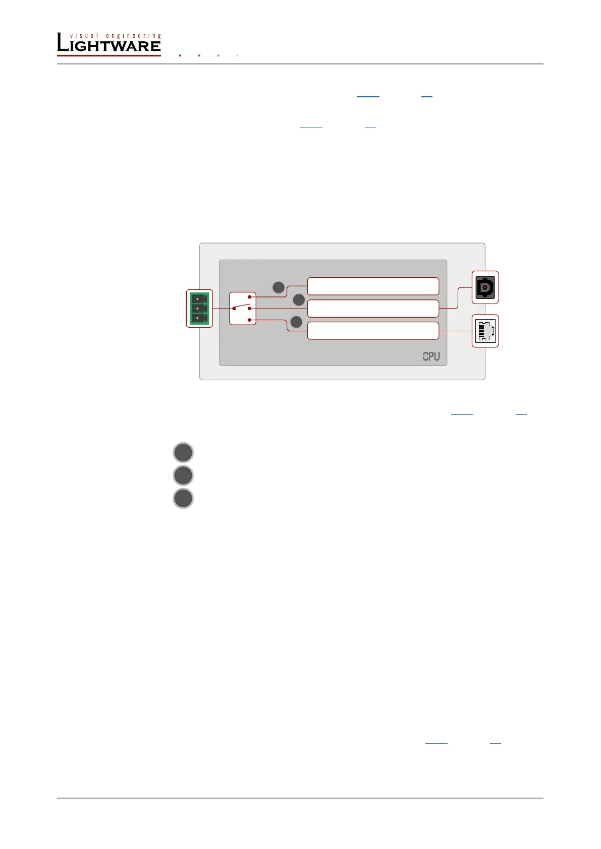
mode, Command Injection mode, or can be Pass-through mode; see the gure below.
The block diagram of the serial interface
All settings are available in the LDC software, see settings in section 6.6.1 on page 39.
The following settings are dened:
1
The Local serial port is in Control mode.
2
The Local serial port is in Pass-through mode.
3
The Local serial port is Command Injection mode.
Control mode
The incoming data from the given port is processed and interpreted by the Microcontroller.
The mode allows to control the transmitter directly. LW2 or LW3 protocol commands are
accepted – depending on the current port setting.
Pass-through mode
In pass-through mode, the given device forwards the data that is coming from one of its
ports to another same type of port. The command is not processed by the CPU. Incomming
serial data is forwarded from one port to another port inside the transmitter.
Command injection mode
In this mode, the transmitter works as an RS-232 bidirectional converter. The optical signal
is converted to RS-232 data and vice versa. Optical port numbers are dened for the serial
ports (optical and local) for this purpose. E.g. the default Command Injection port number
of the local RS-232 port is 8001. If a command is coming from the optical interface which
is address to the port no. 8001, it will be transmitted to the Tx pin of the local RS-232 port.
That works in the opposite direction of course and the method is the same on the serial
interface of the optical port. See the RS-232 settings in section 6.6.1 on page 39.
RS-232
local
port
Local RS-232 / OPT converter
Device Control (Local serial)
CPU
Mode switch
Local
1
2
3
Optical
Local RS-232 / TCP converter
LAN
port
Page 24 / 106 Optical extender concept

Table of Contents

Other manuals for Lightware HDMI-3D-OPT-TX210A

Questions and Answers:

Lightware HDMI-3D-OPT-TX210A Specifications

General IconGeneral
CategoryExtender
Signal TypeHDMI
Input ConnectorHDMI
Input Ports1
Output Ports1
Max Bandwidth18 Gbps
Connector TypeLC Duplex
3D SupportYes
Power Supply5V DC
TypeFiber Optic
Output ConnectorHDMI
Supported ResolutionsUp to 4K@60Hz
Maximum Distance10 km
Transmission Distance100m
HDCP SupportHDCP 2.2
Operating Temperature0°C to +50°C (32°F to 122°F)
Storage Temperature-20°C to +70°C (-4°F to +158°F)
Power Consumption5W

Summary

User's Manual

HDMI-3D-OPT-TX200 Series

Manual title for the HDMI-3D-OPT-TX200 series of extenders.

HDMI-3D-OPT-TX210A

Specific model covered in the manual.

HDMI-3D-OPT-TX210RAK

Specific model covered in the manual.

SW4-OPT-TX240RAK

Specific model covered in the manual.

SAFETY INSTRUCTIONS

Caution: Laser product

Warning regarding potential hazards associated with laser components.

Limited Warranty Statement

1. Introduction

1.2. Description

Overview of the HDMI-3D-OPT-TX200 series extender's capabilities and features.

2. Installation and controls

2.2. Connecting steps

Provides a step-by-step guide for connecting the transmitter to sources and displays.

3. Technologies

3.4. HDCP Management

Information on High-bandwidth Digital Content Protection (HDCP) features and troubleshooting.

4. Optical extender concept

4.2. Video interface

Explains how video crosspoint settings are controlled and port selection methods.

5. Operation

5.2. Software control modes

Overview of available software control methods: LDC, LW2, and LW3 protocols.

6. Software control - Using Lightware Device Controller

6.2. Establishing the connection

Steps to connect the device to a computer using USB, RS-232, or Ethernet.

6.3. Crosspoint menu

Overview of the Crosspoint menu interface within LDC for managing signal routing.

6.4. Port properties and settings

Details on renaming ports, muting, locking, autoselect, and frame detection.

6.5. EDID menu

Interface for managing EDID data, including emulation, learning, exporting, and editing.

6.7. Event Manager

Feature for creating automated actions based on specific conditions.

6.9. Configuration cloning (Backup tab)

Method for backing up and restoring device configurations to save time.

6.10. Advanced view

Interface for running and setting commands not available in the GUI.

7. LW2 programmers' reference

7.3. Port and crosspoint settings

Commands for switching, muting, locking, and managing autoselect for ports.

8. LW3 programmers' reference

8.3. LW3 commands

Detailed explanation and examples of GET, SET, CALL, MAN commands.

8.5. Video port and crosspoint settings

Commands for querying and changing video crosspoint, autoselect, and priority settings.

8.10. EDID management

Commands for managing EDID emulation, copying, deleting, and resetting.

9. Firmware upgrade

10. Troubleshooting

Troubleshooting Common Issues

Guides for diagnosing and resolving common issues with signal transport and display.

Related product manuals