8.5.18. Test pattern generator
The output ports can send a special image towards the sink devices for testing purposes.
The setting is available on output ports with the below-listed parameters.
ATTENTION!
The Mode can be set individually on each port, but the Clock source and the Pattern
settings are common on the local and optical output ports (O1 and O2).
Test pattern generator mode setting:
Command format: SET●/MEDIA/VIDEO/<O
n
>.TpgMode=0|1|2
Response format: pw●/MEDIA/VIDEO/<O
n
>.TpgMode=0|1|2
Parameters:
.TpgMode 0 1 2
Test pattern
generator mode
Disabled
The test pattern
is not displayed
on the output
Enabled
The test pattern
is displayed on
the output
No signal mode
The test pattern is
displayed if there is no
signal on the output port
Example:
˃ SET /MEDIA/VIDEO/O1.TpgMode=2
˂ pw /MEDIA/VIDEO/O1.TpgMode=2
Clock source – the clock frequency of the test pattern
Command format: SET●/MEDIA/VIDEO/<O
n
>.TpgClockSource=480|576|EXT
Response format: pw●/MEDIA/VIDEO/<O
n
>.TpgClockSource=480|576|EXT
Parameters:
.TpgClockSource 480 576 EXT
Clock frequency 480p 576p External clock (from actual TMDS source)
Example:
˃ SET /MEDIA/VIDEO/O1.TpgClockSource=576
˂ pw /MEDIA/VIDEO/O1.TpgClockSource=576
Test pattern
Command format: SET●/MEDIA/VIDEO/<O
n
>.TpgPattern=<pattern>
Response format: pw●/MEDIA/VIDEO/<O
n
>.TpgPattern=<pattern>
Parameters:
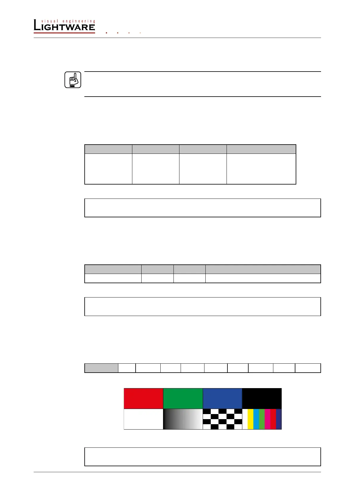
<pattern>
RED GREEN BLUE BLACK WHITE RAMP CHESS BAR CYCLE
Cycle setting means all the patterns are changed sequentially approx. in every 2 seconds.
Example:
˃ SET /MEDIA/VIDEO/O1.TpgPattern=GREEN
˂ pw /MEDIA/VIDEO/O1.TpgPattern=GREEN
Page 78 / 106 LW3 programmers' reference