BOOK CODE
1-5302-556
MODEL No.
50839
DATE OF ISSUE
01-94
REVIEW 02
DATE
30-11-2001
APPROVAL
TECO/ATL AUTHOR
10
19
20
16
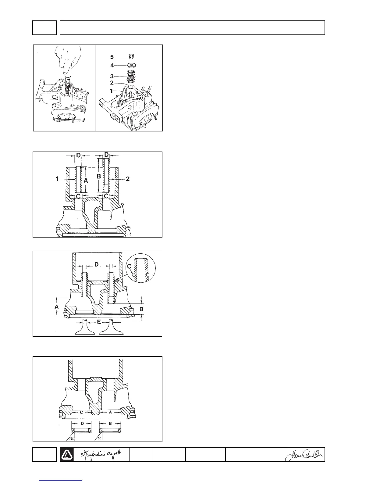
Valves
1 Valve stem
2 Spring holding disk
3 Spring
4 Cap
5 Cotters
Note: In order to remove the cotters, put a shim under the valve
head and strongly press, as shown in picture 16.
Valves guides and housings
1 Exhaust valve guide
2 Intake valve guide
Dimensions (mm):
3LD 450, 3LD 451/S, 3LD 510, 3LD 510/S
A = 43.80 ÷ 44.20 B = 55.80 ÷ 56.20
C = 11.00 ÷ 11.018 D = 11.05 ÷ 11.06
4LD 640, 4LD 705, 4LD 820
A = 47.80 ÷ 48.20 B = 65.80 ÷ 66.20
C = 12.000 ÷ 12.018 D = 12.05 ÷ 12.06
Note: Valve guides with an external dia. increased of 0.5 mm can be
used as spare parts; in this case it is necessary to increase
the housing C of 0.5 mm for the assembly.
Valve guides insertion
Heat the head at 160° ÷ 180°. Force the guides according to A and
B distance with respect to the head surface.
3LD 450, 3LD 451/S, 3LD 510, 3LD 510/S
A = 30.80 ÷ 31.2 B = 18.8 ÷ 19.2
4LD 640, 4LD 705, 4LD 820
A = 35.8 ÷ 36.2 B = 17.8 ÷ 18.2
Note: if the guides are supplied with the housing for the lock ring C,
insert the ring, then drive the guides without worrying about A
and B.
Valve guide dimensions and clearances
3LD 450, 3LD 451/s, 3LD 510, 3LD 510/S (mm):
D = 7.030 ÷ 7.050 E = 6.985 ÷ 7.000
(D-E) = 0.030 ÷ 0.065 (D-E) limit= 0.13
4LD640, 4LD 705, 4LD 820
D = 8.030 ÷ 8.050 E = 7.985 ÷ 8.000
(D-E) = 0.030 ÷ 0.065 (D-E) limit =0.13
Valve housings and seats
3LD 450, 3LD 451/S, 3LD 510, 3LD 510/S (mm);
A = 34.99 ÷ 35.01 C = 30.99 ÷ 31.01
B = 35.10 ÷ 35.12 D = 31.10 ÷ 31.12
4LD 640, 4LD 705, 4LD 820 (mm):
A = 42.99 ÷ 43.01 C = 36.99 ÷ 37.01
B = 43.12 ÷ 43.14 D = 37.10 ÷ 37.12
Drive the seats in the housings and mill at 45°.
18
17
DISASSEMBLY/REASSEMBLYV
 Loading...