DATE
30-11-2001
TECO/ATL AUTHOR
BOOK CODE
1-5302-556
MODEL No.
50839
DATE OF ISSUE
01-94
REVIEW 02
APPROVAL
21
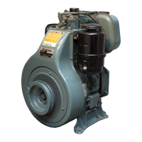
Injection pump assembly
Insert the cylinder 6 in the pump case 7, engaging the slot A in the
eccentric 8.
Insert the delivery valve 4, copper gasket 5, spring 3 O ring 2, then
tighten the fitting at 3.5 ÷ 40 Nm.
Assemble the rack rod 18 and sector gear 9 coinciding points B.
Insert the upper collar 10, spring 11 and piston 12 with reference C
on the same side of the slot A (if it is assembled on the opposite
side, the engine revs out).
Assemble the collar 20, the tappet 13 with rollers 14, 15 and pin
16. While pressing on the tappet, insert the pin 19 and the ring 17.
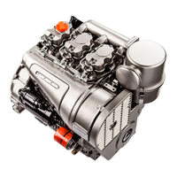
Advanced injection (static)
Disconnect the diesel oil thrust pipe fitting, being careful not to loosen
also the pump delivery fitting 1, then screw the tester for the advanced
injection check 2. Fill the tank, checking that the fuel level is at least 10
cm above the tester. Place the accelerator lever halfway. Turn the
flywheel towards the engine rotation direction and make sure that the
fuel arrives at the tester assembled on the injection pump delivery
fitting. Repeat this operation; during the compression phase, operate
slowly and immediately stop when the fuel moves into the tester hole;
move the flywheel 3 mm back; this is the static advanced injection. If C
does not coincide with B but comes before, add some shims under
the pump, otherwise, remove the shims if C is beyond B.
Note: By removing or adding a 0.1 mm shim under the pump, it is
possible to delay or advance C, which is after B.
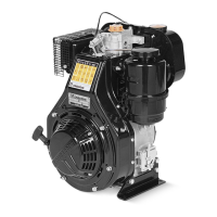
Advanced Injection references on the conveyor and flywheel
protection disk
A Piston reference at top dead centre
B Injection advance reference as to A
A ÷ B Distance in mm
C Reference of piston in injection advance position
a Reference in degrees
D Flywheel protection disk diameter
ENGINES (A-B)mm amm D (3LD)mm D (4LD)mm
3LD 450, 3LD 451/S 58 ÷ 63
3LD 510, 3LD 510/S 24 ÷ 26 276 310
4LD 640, 4LD 705, 4LD 820 65 ÷ 70
4LD 820 at 2600 rpm 60 ÷ 65 22° ÷ 24°
Note: 1
°
stands for 2.7 mm on dia. D= 310 mm; on dia. D = 276 mm,
1
°
stands for 2.4 mm.
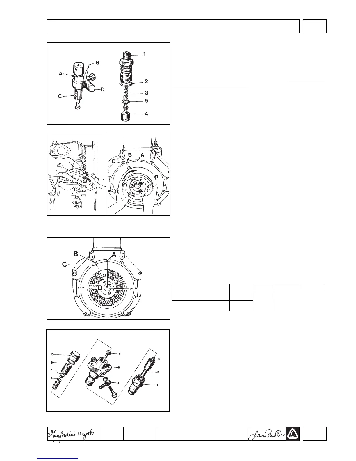
Injector
Components:
1 Ring nut - 2 Nozzle 3 Needle 4 Fitting 5 Nozzle bearing 6 Pressure
rod 7 Spring 8 Spring seat 9 Union 10 Ring nut
Setting
Connect the injector to a manual pump and check that the setting
pressure is 190 ÷ 200 bars. If necessary adjust, actuating the
union 9.While replacing the spring, the setting shall be carried out
at a pressure higher than 10 bars (200 ÷210 bars) in order to
counterbalance the running adjustments. Check the needle valve
seal by slowly activating the manual pump up to abt. 170 bars. In
case of dripping, replace the nozzle. Tighten the injector to the head
at 15 Nm for 3LD 450, 3LD 451/S, 3 LD 510, 3 LD 510/S and at 20
Nm for 4LD 640, 4LD705, 4LD 820.
Note: A new injector is currently assembled, its components are
different, though the setting remains the same.
71
74
75
72
73
VIIFUEL/INJECTION CIRCUIT
 Loading...