BOOK CODE
1-5302-556
MODEL No.
50839
DATE OF ISSUE
01-94
REVIEW 02
DATE
30-11-2001
APPROVAL
TECO/ATL AUTHOR
8
9
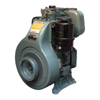
Starting pulley
In order to carry out any easier staring, it is necessary to place the
driving shaft at the TDC (Top dead center) and to assemble the pulley
with notch 1 moved back at ( 45°) according to the rotation direction of
the engine, as per picture 4 and 5 .
Tighten the screws at 35 Nm for 3LD 450, 3LD 451/S, 3LD510, 3LD
510/S, at 40 Nm for 4LD 640, 4LD 705, 4LD 820.
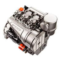
Vent plug
Components
1 Vent plug and oil refiling
2 O-ring
3 Diaphragm
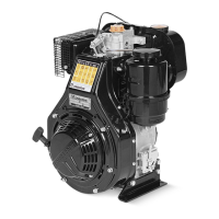
Valve/rocker arm clearance
Place the piston at the compression top dead centre.
Place thickness gauge 1 between the valve stem and the rocker
arm; cold-adjust the clearance at 0.15 ÷0.20 mm for both valves.
Tighten the rocker arm box cap at 20 Nm.
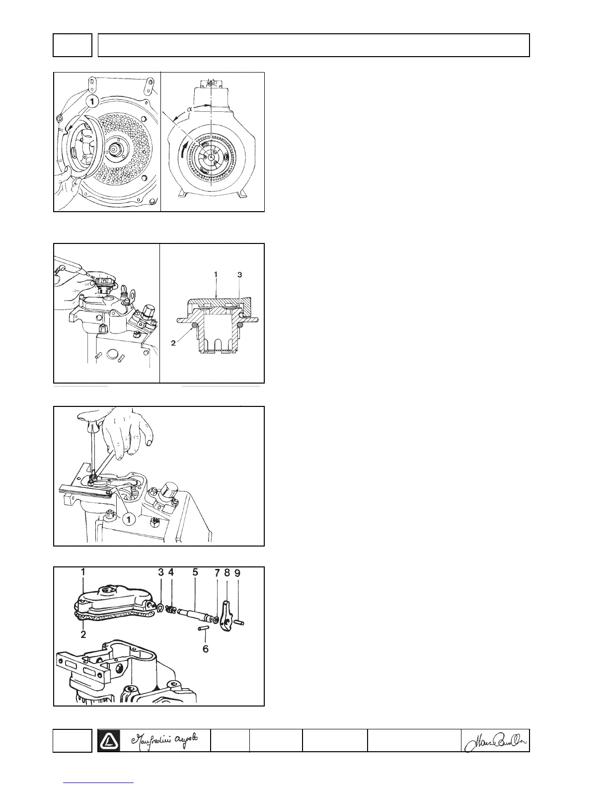
Decompression (by request)
Components:
1 Cover 6 Pin
2 Gasket 7 Ring
3 Lock ring 8 Lever
4 Spring 9 Pin
5 Shaft
The engine rocker arm cover can be equipped with a
decompression device which compresses the exhaust valve at the
TDC (top dead centre), lowering it of abt. 1mm. during the starting
phase. The lowering is adjusted by the gaskest thickness 2. Make sure
that the lever turns for abt. half a stroke before it actuates the valve.
Warning!
The use of decompression to stop the engine may cause serious
damages.
4
6
8
5
7
V
DISASSEMBLY/REASSEMBLY
 Loading...