BOOK CODE
1-5302-556
MODEL No.
50839
DATE OF ISSUE
01-94
REVIEW 02
DATE
30-11-2001
APPROVAL
TECO/ATL AUTHOR
22
76
77
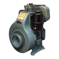
VIII ELECTRIC CIRCUIT
12 V 14 A electrical ignition, diagram with voltage regulator ,
battery recharge lamp and manostat
Components:
1 Alternator
2 Starting motor
3 Voltage regulator
4 Battery
5 Oil pressure switch
6 Oil pressure lamp
7 Ignition switch
8 Battery recharge lamp
Note: The batteries, which are not supplied by Lombardini, shall
have a 12 V voltage and the following capacity:
3LD 450, 3lD 451/S, 3LD 510, 3LD 510/S = 45 Ah
4LD 640 = 55 Ah
4LD 705 = 66 Ah
4LD 820 = 70 Ah
12.5 V 14 A alternator
It is equipped with a fixed rotor assembled on the main journal,
while the pivoting rotor is housed inside the flywheel.
Dimensions (mm):
A = 159
B = 44.5
C = 4
D = 28.5
Note: The clearance between inductor and rotor (air gap) shall be
0.5 ÷ 0.6 mm.
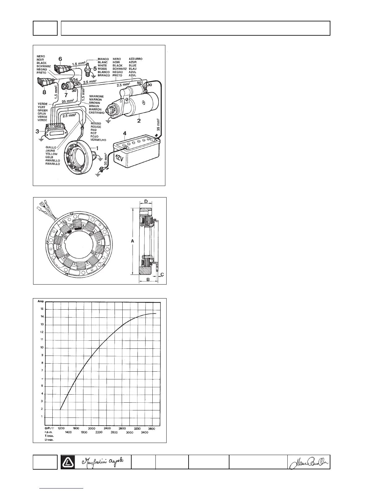
12,5 V, 14 A alternator battery recharge curve
It is carried out at + 25° C ambient temperature, 12.5 V battery
voltage.
78
 Loading...