- 31 -
FOCS Workshop Manual_cod. 1.5302.351_7° ed_ rev. 06
4
10
11
9
12
5
5
6
4
9
6
4
Disassembly / Reassembly
E.G.R. Circuit
Operation
The main function of the E.G.R. (Exhaust Gas Recirculation)
system is the reduction in emission of NOx (nitrogen oxides), gases
harmful to people and the environment, via lowering the
combustion temperature.
The system takes a certain quantity of exhaust gas from the
exhaust manifold 1 (fig. 8) via the E.G.R. pipe (2) to the E.G.R.
valve 3.
This valve is opened by the vacuum (created in pipes 6, 7, 8 and 9
by vacuum pump 4; fig. 8) only when:
a) thermovalve 10 placed in contact with the engine refrigerant
fluid reaches a temperature of 40 °C;
b) the on-off sensor control cam 12 opens the vacuum valve 11 at
a determined accelerator position.
Once the E.G.R. valve is opened, the exhaust gas enters the intake
manifold 13 via the intake flange.
The same logic controls the closure of the E.G.R. valve.
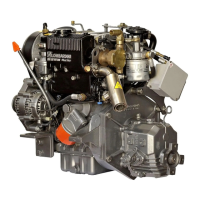
Disassembly:
- Disengage the control rod catch (1) with a screwdriver from the
accelerator control rod (2) (fig. 9).
- Disconnect the accelerator control rod (2) from the accelerator
control lever (3) (fig. 9).
- Disconnect the thermovalve – vacuum pump connection pipes
(7, fig. 8) and vacuum valve – thermovalve connection pipe (8,
fig. 8) from the thermovalve.
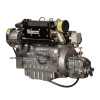
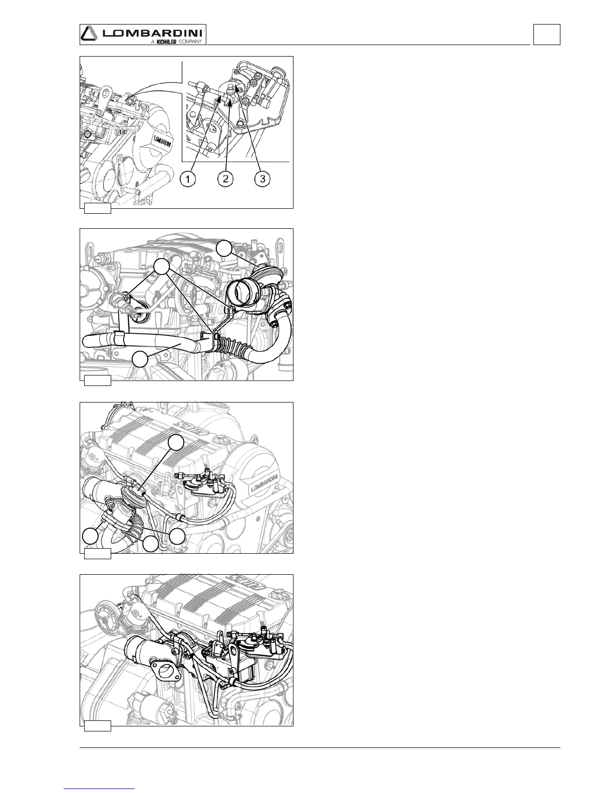
- Unscrew the two fastening screws (5) that fix the E.G.R. pipe (6)
to the E.G.R. valve (4) (figures 10, 11 and 12).
- Remove the intake manifold. See "Intake manifold – Remote air
filter" on page 30 (Figure 7).
- Unscrew the fastening screw of the E.G.R. pipe support bracket
(9 fig. 10) from the engine crankcase and disengage the E.G.R.
pipe from the exhaust manifold.
Reassembly:
When reassembling pay attention to the repositioning of the
gaskets and to the precise connection of the pipes (6, 7, 8, 9, fig.
8).
These pipes should be carefully fitted on the appropriate
connections.
Tighten the screws to specified torque, see "Table of tightening
torques for the main components" on page 100.
 For the calibration of the E.G.R. system see "E.G.R. calibration"
on page 97.

 Loading...