- 59 -
FOCS Workshop Manual_cod. 1.5302.351_7° ed_ rev. 06
120 121
4
122
124
125
123
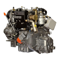
Connecting rod alignment
Utilizzare un calibro con piano di riscontro o un comparatore come
in figura.
Controllare l'allineamento degli assi utilizzando lo spinotto del
pistone; lo scarto A = 0,015 mm;. limite 0,030 mm.
Piccole deformazioni si possono correggere sotto una pressa
agendo con sforzi graduali.
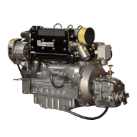
CYLINDERS
Reset the dial gauge with a calibrated ring: check the diameter D in
points 1, 2 and 3; repeat the same operation rotating the dial gauge
by 90° at the same heights.
Check any wear in zone X where the piston rings operate and if it is
greater than the 0.05 mm max limit given adjust the cylinder to the
next increased value.
72,000 mm for LDW 502-602-903-1204-1204/T engines;
75,000 mm for LDW 702-1003-1404 engines.
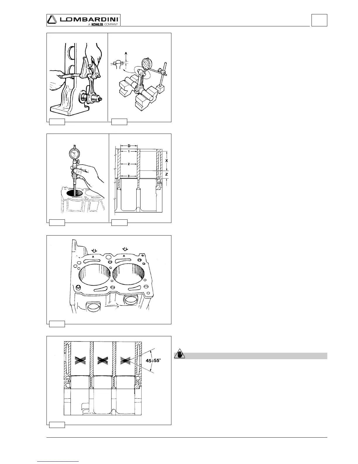
Cylinder roughness
Caution – Warning
Do not treat the cylinder’s internal surfaces with an emery
cloth.
The angle of the crossed processing marks must be between 45°
and 55°. These must be uniform and distinct in both directions.
Average roughness must be between 0.5 and 1 µm.
The whole surface of the cylinder affected by contact with the piston
rings must be rendered with the plateau method.
Cylinder, class
The pistons (A, B, C) locations are shown on the piston crown
while those for the cylinders are found on the crankcase in the
points shown by the arrows, see picture.
Note: For LDW 502 with an aluminium crankcase, the cast iron
cylinders can be adjusted normally to increase values by 0.5
and 1.0 mm.
The cylinders are not to be changed.
Disassembly / Reassembly

 Loading...