- 82 -
FOCS Workshop Manual_cod. 1.5302.351_7° ed_ rev. 06
188
189
8
190 191
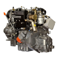
Static injection advance regulation
Fill the tank and operate the fuel pump.
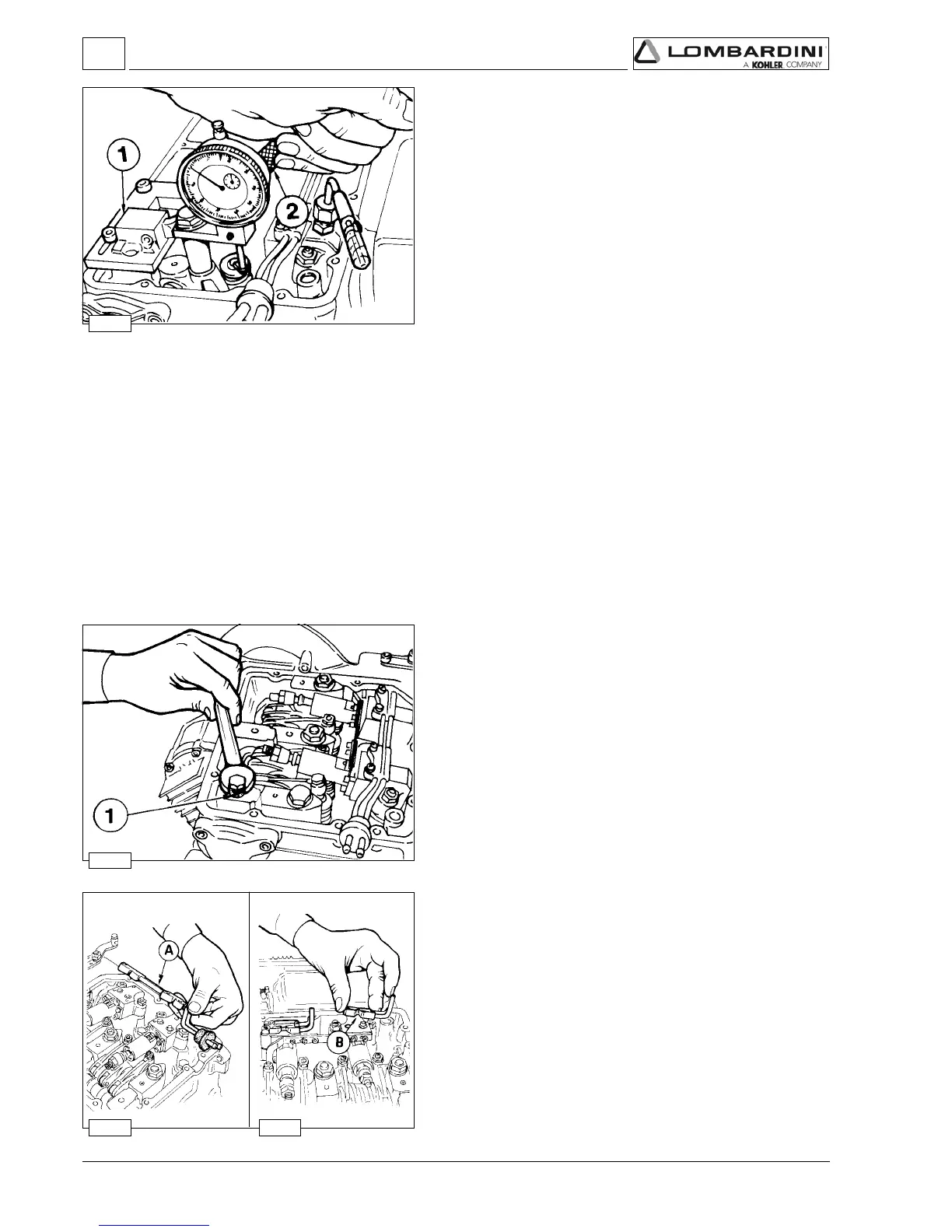
Set the pump/injector delivery control rod (ref. A fig. 187) at half-
stroke.
Bring the piston to the top dead centre of compression. Fit a 13
mm hexagon wrench on the injection advance adjusting screw lock
nut. By turning the wrench forth and back you prime the injection
pump, thus enabling the tester to be drained.
With the piston at its TDC, operate lever 2 fig. 188 and bring the
drain valve into contact with the piston. Then reset dial gauge.
Go back ¼ of a turn moving the crankshaft anticlockwise. Then
turn forward again very slowly
observing the fuel level inside the tester. As soon as the level
changes, then stop. You reached the static injection advance.
By actuating lever 2 check piston lowering with respect to the TDC
that shall be between 0.89 and 1.24 mm for LDW 602-903-1204,
and between 0.73 and 1.02 for LDW 502 engine model.
The table on page 80 shows both piston lowering expressed in mm,
with respect to the TDC, and the corresponding rotation of the
crankshaft, expressed in degrees.
The static injection advance in degrees
αα
αα
α = 11° to 13° refers to all
engines for adjustments from 1500 / 3600 rpm.
Test head B assembly
Remove fuel pipe A and mount one test head B in its place per
pump/injector.
The test heads complete with pipes are supplied together with
instrument ref. 7104-1460-069.
Preliminary steps to pump/injector unit delivery balancing test
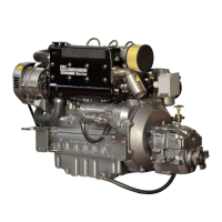
Closing the oilhole
To perform this test you must remove the rocker arms cover and
close hole 1 with an M 8x1.25 or M 10x1.5 screw (on latest model
engines) not longer than 8 mm. Also remove the copper gasket.
If the camshaft and rocker arms are dry, lubricate them with engine
oil.
Note: If you only want to check the nozzle it is not necessary to
balance the deliveries; provided that when you dismount the
rod you do not loosen adjusting screws 1 and 2 (fig. 193).
Fuel system

 Loading...