REG. CODE
1-5302-351
MODEL N°
50563
DATE OF ISSUE
04.90
REVISION 04
DATE
15.11.99
ENDORSED
COMPILER TECO/ATI
40
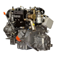
VALVE / ROCKER COVER: All critical engine adjustments require
the removal of the valve/ rocker cover. Remove the valve / rocker
cover by removing the crankcase vacuum regulator valve (see
below), removing the retaining bolts, then lifting the valve / rocker
cover assembly.The engine crankcase breather system is integrally
contained by the valve / rocker cover. Additionally, the valve / rocker
cover facilitates oil pressure measurement and camshaft/ rocker
arm lubrication via oil ports.
Components:
INSPECTION / CLEANING: Inspect the valve/ rocker cover for
clogged oil ports, varnish deposits, cracks and lack of parallelism at
the mounting flange. Remove boot(4) ,clean in solvent and dry
(COMPLETELY) with compressed air. Replace the boot (4) if
swelling, cracking or degradation is noted.
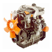
CRANKCASE VACUUM REGULATOR VALVE (602, 702, 903,
1003, 1204, 1204/T, 1404)
The LDW-FOCS crankcase breather system is closed loop design.
Therefore, all crankcase vapors are induced into the intake manifold
and consumed by the engine. As such, a crankcase vacuum
regulator is required so that in conditions of high air filter restriction,
excessive oil is prevented from entering the engine potentially
causing speed regulation problems.
Components:
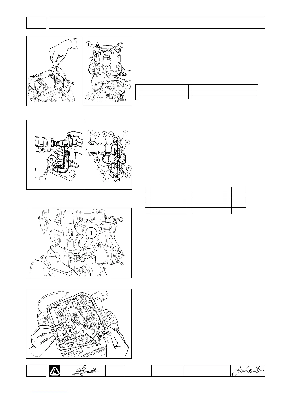
CRANKCASE BREATHER - LDW 502
The crankcase breather system of the LDW 502 is not integral with
the valve/ rocker cover as described above. The LDW 502 breather
system includes a breather assembly(1), which includes a vapor
separation, condensate drain and vacuum regulator. A hose (not
shown) connects the breather assembly to the intake manifold.
VALVE / ROCKER COVER GASKET
The FOCS valve/ rocker cover gasket (A) is a critical part of the
lubricating system. Always replace the valve / rocker cover gasket
when reinstalling the valve / rocker cover.
Thoroughly clean all gasket material from the cylinder head and
valve / rocker cover. Place a small bead of RTV Silicone at positions
(1) and (2). Install the valve / rocker cover gently, inserting the drain
boot (see top diagram, No. 4) into the cylinder head. Torque the
valve / rocker cover bolts to 9 Nm.
1 Oil Pressure Switch 4 Boot/ Tube for oil return to the Oil Sump
2 Camshaft Lubrication Port 5 Crankcase Ventilation Chamber
3 Rocker Arm Lubrication Port
1 Gland Nut 6 Clip / Lock 11 Spring
2 Bushing 7 O-Ring 12 Tube
3 Body 8 Washer 13 Hose
4 Diaphragm 9 O-Ring
5 Cap/ Cover 10 Valve
DISASSEMBLY/REASSEMBLY
II

 Loading...