COMPILER TECO/ATL
REG. CODE
1-5302-351
MODEL N°
50563
DATE OF ISSUE
04.90
REVISION 04
ENDORSED
DATE
15.11.99
51
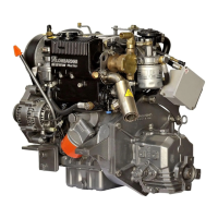
CONNECTING ROD ALIGNMENT
Check the alignment of the connecting rod wrist pin bore with
respect to the connecting rod journal diameter by fitting the
connecting rod to a suitable fixture as shown or by placing the
connecting rod on a mandrel in V-blocks as shown. If the V-block
and dial indicator method is used, center the wrist pin in the
connecting rod wrist pin bore so that an equal amount of the wrist
pin protrudes from each side of the connecting rod. While holding
the wrist pin down and seated in the wrist pin bushing, measure the
height of the wrist pin on both sides of the connecting rod. If the
fixture method is used, press down on the wrist pin as shown and
measure the any axial offset.
Maximum Axial Mis-alignment = .015mm (USEABILITY Limit =
0.030mm)
Minor mis-alignment may be corrected by skillfully and gradually
working the connecting rod between centers on a press. DO NOT
ATTEMPT TO CORRECT MIS-ALIGNMENT UNLESS PROPERLY
TRAINED AND EXPERIENCED.
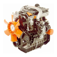
PISTON WRIST PIN INSTALLATION / RETAINING SNAP RING
After thoroughly cleaning and checking the connecting rod as
described in the previous, liberally coat the wrist pin , piston wrist pin
bore and wrist pin bushing with clean engine oil. While holding the
piston and connecting rod as shown, insert the wrist pin into the
piston and through the connecting rod. Do not force the wrist pin or
use a hammer or drift pin to install the wrist pin. If hand force cannot
install the wrist pin, investigate the cause of the problem.
Install the piston pin retaining pin so that the open ends of the snap
ring are oriented as shown in the diagram. The radial distance
between the piston centerline and the open ends of the snap ring
should be equal on both sides. The snap ring may be moved into
proper position after installation by carefully acting on the snap ring
with a suitable awl at point(A).
CONNECTING ROD- PISTON ASSEMBLY BALANCE
Weigh the connecting rod / piston assemblies to be installed with a
given engine. The maximum allowable weight difference between the
lightest and heaviest assembly is 10 grams.
If the 10 gram differential in weight cannot be achieved, exchange
pistons and/ or connecting rods until the maximum differential is 10
grams or less.
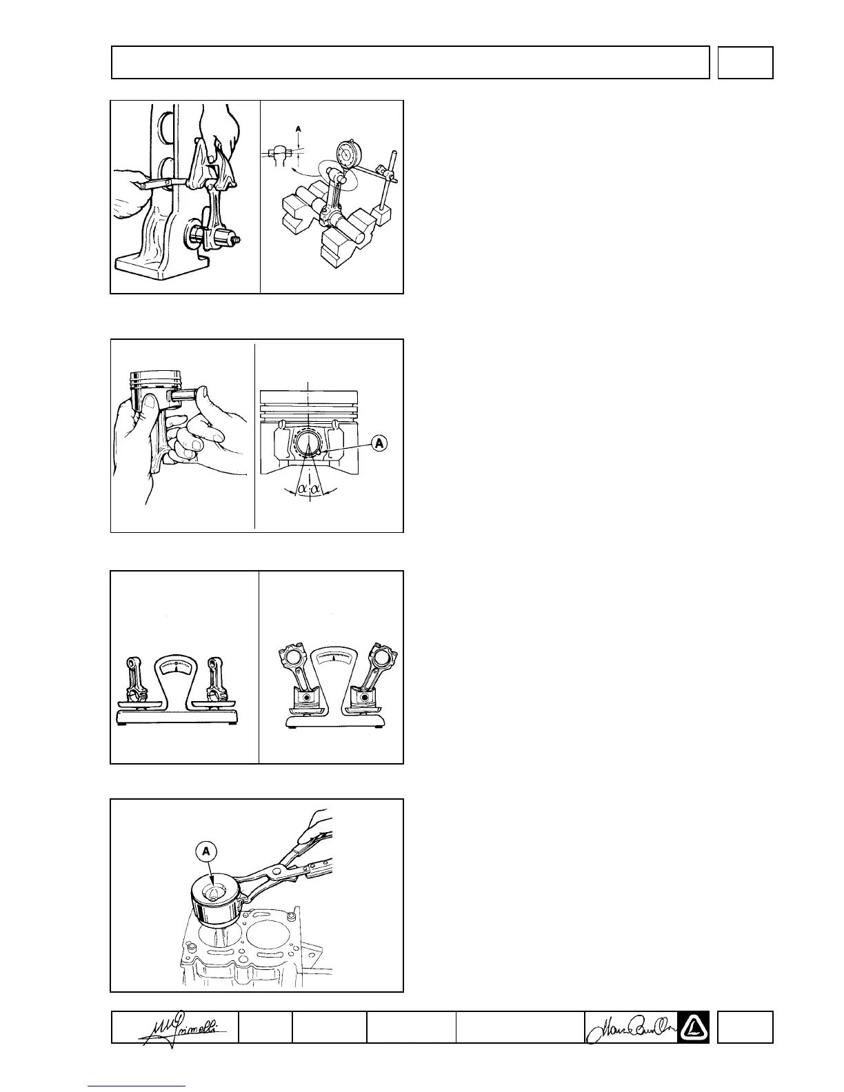
PISTON / CONNECTING ROD INSTALLATION
With reference to the cylinder bore and preparation specifications on
page 38 and the information presented prior regarding pistons,
piston rings and connecting rods, install the piston / connecting rod
assembly.
Rotate the engine so that the respective cylinder for piston/
connecting rod installation is at BDC. Clean the crankshaft rod
journal. Coat the rod journal with clean engine oil. Remove the
connecting rod cap. Install the upper and lower connecting rod
bearings (see page 41). Liberally coat the connecting rod bearings,
cylinder, piston and piston rings with clean engine oil. Rotate the
piston rings to insure that no ring end gap is located on the thrust
side of the piston (90° ± 10° from the wrist pin axis) and that all ring
end gaps are spaced approximately 120° relative to each other.
Compress the piston rings with a suitable tool as shown. Orient the
piston so that the turbulence chamber(A) in the top of the piston will
correspond to the pre-combustion chamber in the cylinder head.
Gently lower the piston / connecting rod assembly into the cylinder
taking extreme care not to cock the piston in the bore and preventing
the connecting rod from contacting the crankshaft. Gently tap the
center of the piston with the wooden end of a light hammer while
guiding the connecting rod over the crankshaft journal.
DISASSEMBLY/REASSEMBLY
II

 Loading...