REG. CODE
1-5302-351
MODEL N°
50563
DATE OF ISSUE
04.90
REVISION 04
DATE
15.11.99
ENDORSED
COMPILER TECO/ATI
56
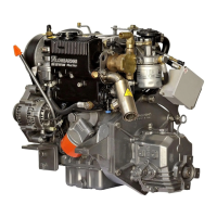
Front Crankshaft Seal Rear Crankshaft Seal
CRANKSHAFT SEALS - FRONT and REAR
The front seal for the FOCS diesel engine is housed within the oil
pump assembly. The rear oil seal is supported by the rear oil seal
support. Lombardini recommends that oil seals be replaced if
removed from the supporting bores. The oil seals should also be
replaced if upon inspection, signs of hardening, stress cracks,
dampness on the exterior or dry rot is noted.
SEAL DETAILS:
A Seal Support
B Seal
1 Installation depth plane (initial), front
2 Installation depth plane (initial), rear
3 Crankshaft wear surface- front
4 Crankshaft wear surface- rear
INSTALLATION: Remove the oil pump or seal support depending
upon front or rear seal replacement. Gently, without deforming the
seal supporting bore, pry the seal from the bore. Carefully clean, in a
non abrasive manner, the wear surface of the crankshaft. Soak the
oil seal in clean engine oil for approximately 1/2 hour. Coat the
crankshaft with clean engine oil. Using a suitable mandrel, evenly
and squarely push the seal into the bore until the outer seal plane
coincides with planes (1) or (2). Reinstall the oil pump or seal
support using new gaskets as required. Torque the rear seal support
retaining bolts to 12 Nm. Torque the oil pump retaining bolts to 25
Nm.
NOTE: If the wear surface of the crankshaft showed signs of
grooving at the initial installation depth reference (1) or (2), push the
seal into the bore an additional 2mm using a suitable mandrel.
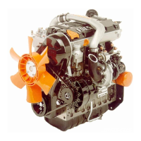
CRANKSHAFT LUBRICATION DRILLINGS- TYPICAL
The lubrication drillings for the LDW 502(A) and LDW 602-702(B)
are shown in the diagram. The lubrication drillings for the LDW 903,
LDW 1204 and LDW 1204T are very similar to the LDW 602-702.
CLEANING: Remove plugs at (1) and (4) by suitable means. Soak
the crankshaft in solvent to loosen any deposits within the drillings.
Clean the drillings (1), (2), (3), and (4) by blowing with compressed
air, using stem brushes, etc.. Cap the drillings at (1) and (4) with new
plugs.
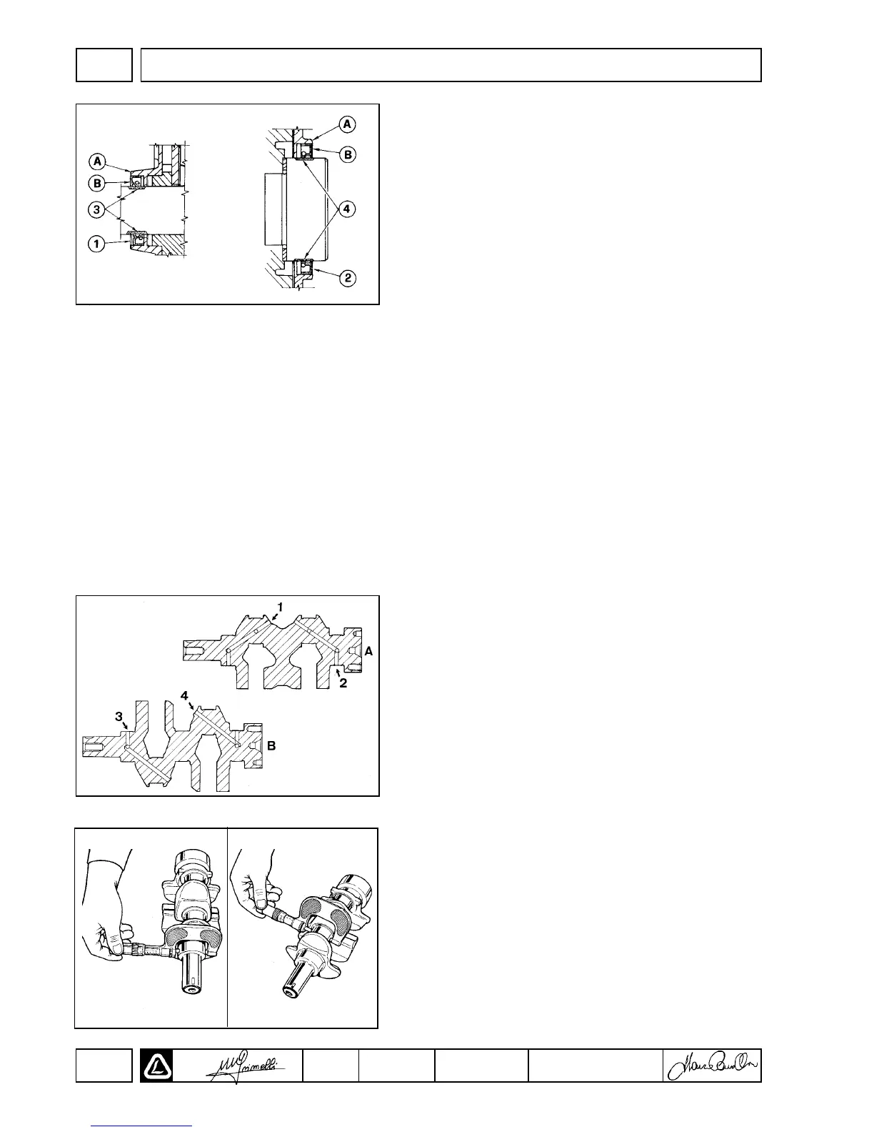
CRANKSHAFT JOURNAL INSPECTION / MEASUREMENT
INSPECTION: Inspect each journal (main and rod) for scratches,
scoring, grooves and general wear. Replace the crankshaft or
machine as required. See page 456for dimensional specifications.
MEASUREMENT: With reference to the diagram, measure each
journal with a calibrated micrometer. Each journal should be
measured at 45° intervals around the circumference of each journal
beginning at the position shown on the left most diagram. At each
interval, measure two seperate parts of the given diameter- once
near the center of the journal and once near the fillet of the journal.
DISASSEMBLY/REASSEMBLY
II

 Loading...