REG. CODE
1-5302-351
MODEL N°
50563
DATE OF ISSUE
04.90
REVISION 04
DATE
15.11.99
ENDORSED
COMPILER TECO/ATI
44
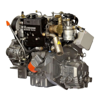
CAMSHAFT LOBE SPECIFICATIONS
NOTE: The camshaft shown in the figure is reflective of a LDW 903.
However, the cam lobes are identical for the LDW 502, LDW 602,
LDW 903 and LDW 1204 diesel engines. The cam lobes are slightly
different for the LDW 1204/T as is shown in the data below.
H- (502, 602, 903, 1204)= Valve Lobe (intake/ exhaust)= 29.598/
29.650mm
H- 1204/T, Intake Lobe= 29.438/29.490mm
H- 1204/T, Exhaust Lobe= 29.778/29.830mm
H- USEABLE Limit (All Models)= Minimum Value minus(-) 0.1mm
H
1
- Injection Lobe (All Models)= 28.948/29.00mm
H
1
- Injection Lobe USEABLE Limit= 28.848mm
LOBE IDENTIFICATION:
CYLINDER HEAD REMOVAL
Remove all cylinder head bolts, then lift the cylinder head from the
crankcase. Do not pry excessively, lever or strike the cylinder head
with a hammer in attempts to break the cylinder head loose from the
head gasket. Do not damage the pre-combustion chambers during
the handling process.
INSPECTION: Thoroughly clean the cylinder head in a non-caustic
solvent. Dry with compressed air. Inspect for cracks and warpage.
Check cylinder head warpage using a high quality straight edge and
precision feeler gauges. Hold the straight edge on the cylinder head
deck and check corner-to-corner and side to side in at least four(4)
equidistant zones. The maximum allowable warpage is 0.10mm. If
warpage exceeds 0.10mm, the cylinder head may be planed a
maximum of 0.20mm. NOTE: Remove pre-combustion chambers
before planing.
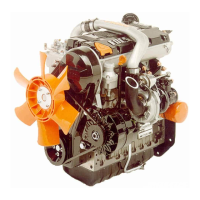
VALVE REMOVAL
Components:
Place the cylinder head on suitable wood spacers so that the pre-
chambers do not touch the top of the work bench when the cylinder
head is oriented as shown. Using a suitable valve spring
compression tool and acting on the spring cap(5), compress the
valve springs so that the collets(6) can be removed while the spring
is being held in the compressed state. WARNING: Valve springs can
store a considerable amount of energy while under compression.
Compress and hold valve springs under compression with care- wear
suitable eye protection. After the collets are removed from all valves,
turn the cylinder head 90° so that the cylinder head is resting on the
intake or exhaust planes. Remove the valves. If valves are to be
reused, label each valve according to cylinder number so that the
valves can be reinstalled in the identical position as removed.
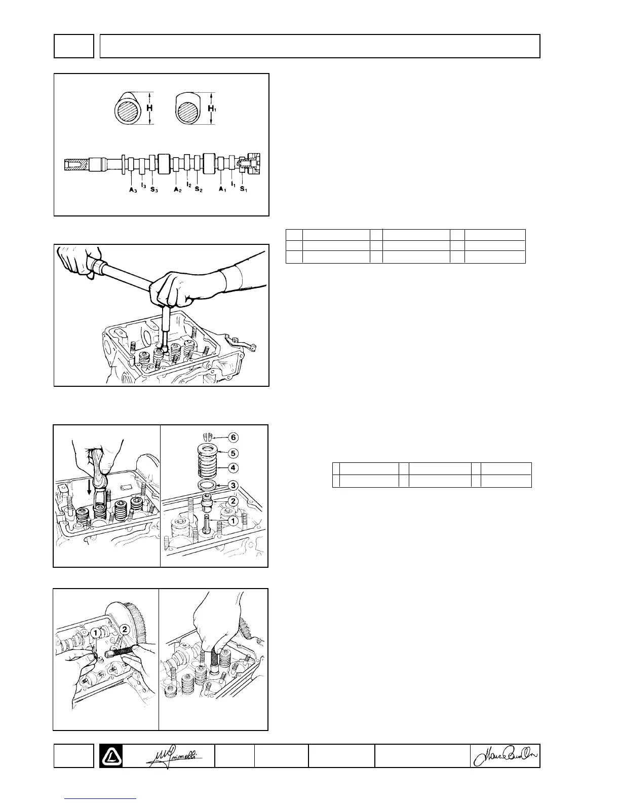
VALVE STEM SEAL INSTALLATION
Following cleaning of the cylinder head and machining or lapping of
the valves/ valve seats, install the valves into the cylinder head.
Using wooden spacers to prevent pre-chamber damage, orient the
cylinder head as shown. Soak new valve stem seals in clean engine
oil for five(5) minutes. Liberally lubricate the valve stems with clean
engine oil. Using special tool 1460-047, place the valve stem seals in
the end of the 1460-047 tool. Carefully push the valve stem onto the
valve stem and over the valve guide. Do not force the seal or use a
hammer to drive the seals into place. The hand force applied must be
parallel to the valve
A1 No. 1 Intake A2 No. 2 Intake A3 No. 3 Intake
S1 No. 1 Exhaust S2 No. 2 Exhaust S3 No. 3 Exhaust
I1 No. 1 Injection I2 No. 2 Injection I3 No. 3 Injection
1 Valve Stem 3 Spring Seat 5 Spring Cap
2 Valve Seal 4 Spring 6 Collets
DISASSEMBLY/REASSEMBLY
II

 Loading...