COMPILER TECO/ATL
REG. CODE
1-5302-351
MODEL N°
50563
DATE OF ISSUE
04.90
REVISION 04
ENDORSED
DATE
15.11.99
73
FUEL SYSTEM
VI
UNIT INJECTOR DELIVERY EQUALIZATION- PREPARATION
Due to the fact that unit injectors are both injection pump and injector, all unit
injectors within a FOCS diesel engine must be equalized to facilitate the
identical delivery of fuel within individual cylinders. The equalization procedure
is a operational test with the valve cover removed. Therefore, proper eye
protection must be worn and great care must be taken to insure no body or
clothing contact with rotating engine components.
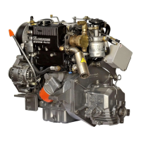
After carefully removing the engine valve cover, install a M8x1.25x10mm
capscrew and 8mm copper gasket at position(1) as shown. Failure to install
the bolt as shown will result in a large scale oil spill and loss of oil pressure to
the engine during the operational procedure presented below.
NOTE: SEE PAGE 74 FOR INITIAL INJECTOR CONTROL RACK AND
GOVERNOR ADJUSTMENT PROCEDURES.
UNIT INJECTOR DELIVERY EQUALIZATION- PREPARATION (cont.)
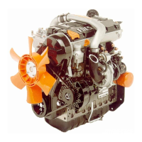
Remove the fuel manifold assembly(A). In place of the fuel manifold, install
on each unit injector a test head(B). The test heads are supplied as part of
the equalization tool package. Please note that early versions of the unit
injector and late versions of the unit injector require different test heads.
Please refer to page 56 for further details.
EQUALIZATION TOOL INSTALLATION, PLUMBING
Place the equalization tool on a stable surface , with the base of the
equalization tool at least 20cm higher than the level of the unit injectors.
Close all valves(2,3). Remove fuel cap(6) and fill the reservoir with clean
diesel fuel. With reference to the diagram, connect the lower hoses
(A)coming from the equalization fixture to the test head position(A). The
hoses should be connected to the test heads in a logical manner. That is, the
left most hose should be connected to No. 1 unit injector (flywheel side), then
subsequent hoses from left to right, connected to cylinders 2, 3, 4 as
required. Connect the upper hoses(B) to the test head position (B). Make
sure that the control lever(4) is in the upper position.
After completion of the hose routing/ plumbing, open the valves (2,3). Start
the engine and allow to idle. Increase and lock the engine speed to 1500 rpm.
Once the engine operates smoothly and the 1500rpm is reconfirmed, pull the
control lever(4) downward for approximately one(1) minute. While closely
watching the fuel level in the cylinder tubes(5), note the rate at which fuel is
consumed. NOTE:, the control lever(4) must be returned to the upper
position prior to fuel depletion in the tubes(5).
During operation with the control lever down, determine the cylinder(s) which
are consuming more fuel as indicated by the speed at which the fuel is
depleted from each individual tube(5). Delivery rates in each cylinder should
be within 2 cm
3
during one(1) minute of operation. Reduce the fuel delivery
rate to the cylinder(s) consuming the most fuel. Delivery may be adjusted as
follows:
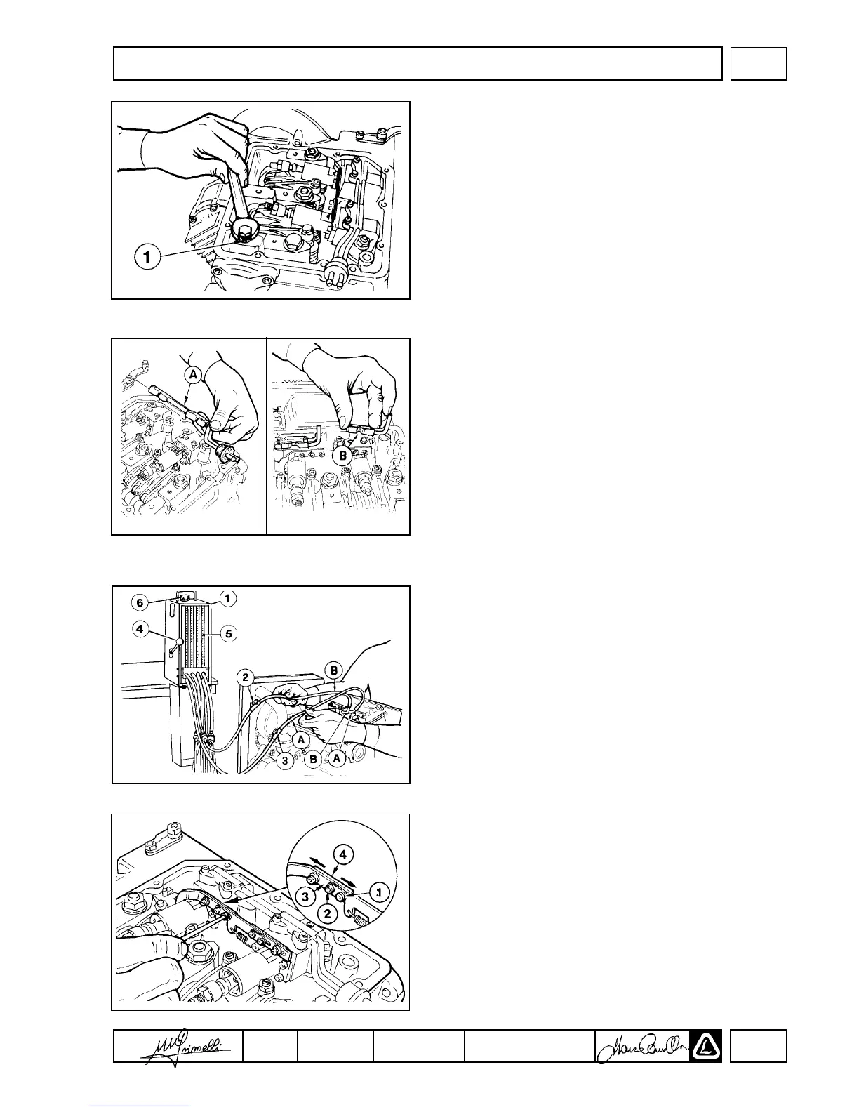
FUEL RATE ADJUSTMENT DETAILS
To increase the fuel delivery of an individual unit injector, the injector rack
must be moved slightly toward the flywheel end of the engine. With reference
to the figure on the left, loosen screws (1) and (2) 1/2 turn. Increase the
cylinder fuel delivery by moving plate (4) slightly towards the flywheel, thus
changing the relative position of control rod (3). Reductions in fuel delivery
can be facilitated by moving the plate away from the flywheel. After
adjustment, torque screws (1) and (2) to 1.1 Nm.
Repeat the equalization test until the individual cylinder fuel consumptions are
within 2 cm
3
during a one(1) minute period.
NOTE: The equalization procedure should be performed following an injector
re

 Loading...