Valve actuating gear
Drive of the push rod for the inlet and exhaust
valves is from the camshaft via inlet and exhaust
rocking levers supported on a joint pillow, with the
cam movements being transmitted via a follower.
The push rod movement is in the cylinder head
transmitted to short rockers, and from these to a
guided, spring-loaded yoke. This yoke operates two
equal valves each.
The pillow supporting the rocking levers (the rocking
lever casing) is bolted to the cylinder head.
Bearing bushes, ball pans and yokes are lubricated
by means of a fitting in the pillow.
Fuel injection system
The engine is provided with one fuel injection pump
unit, an injection valve, and a high pressure pipe for
each cylinder.
The injection pump unit is mounted on the engine
frame. The pump unit consists of a pump housing
embracing a roller guide, a centrally placed pump
barrel and a plunger. The pump is activated by the
fuel cam, and the volume injected is controlled by
turning the plunger.
The fuel injection valve is located in a valve sleeve in
the centre of the cylinder head. The opening of the
valve is controlled by the fuel oil pressure, and the
valve is closed by a spring.
The high pressure pipe which is led through a bore
in the cylinder head is surrounded by a shielding
tube.
The shielding tube also acts as a drain channel in
order to ensure any leakage from the fuel valve and
the high pressure pipe will be drained off.
The complete injection equipment including injec-
tion pumps and high pressure pipes is well
enclosed behind removable covers.
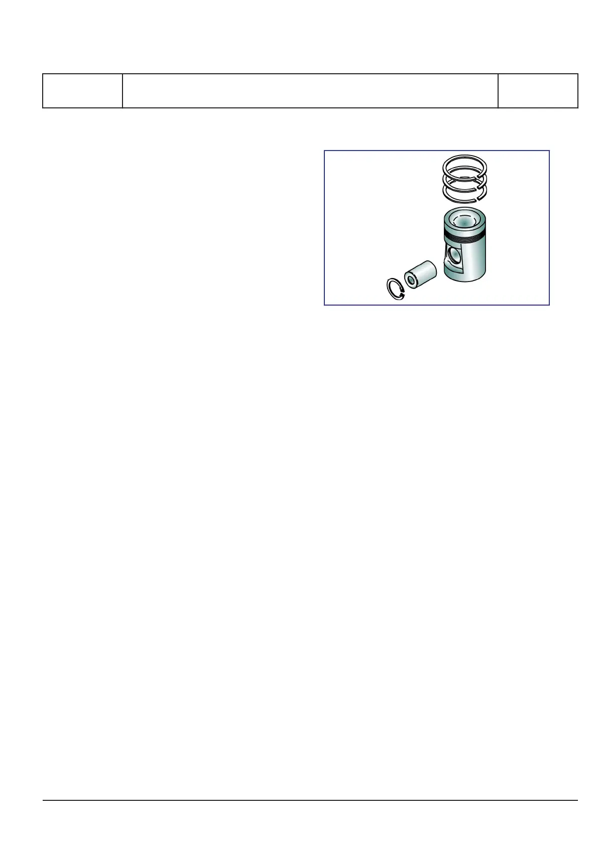
Piston
The piston, which is oil-cooled and of the compo-
site type, has a body made of nodular cast iron and
a crown made of forged deformation resistant steel.
It is fitted with 2 compression rings and 1 oil scraper
ring in hardened ring grooves.
Figure 4: Piston
By the use of compression rings with different bar-
relshaped profiles and chrome-plated running surfa-
ces, the piston ring pack is optimized for maximum
sealing effect and minimum wear rate.
The piston has a cooling oil space close to the pis-
ton crown and the piston ring zone. The heat trans-
fer, and thus the cooling effect, is based on the
shaker effect arising during the piston movement.
The cooling medium is oil from the engine's lubri-
cating oil system.
Oil is supplied to the cooling oil space through
channels from the oil grooves in the piston pin
bosses. Oil is drained from the cooling oil space
through ducts situated diametrically to the inlet
channels.
The piston pin is fully floating and kept in position in
the axial direction by two circlips.
Connecting rod
The connecting rod is of the marine head type.
The joint is above the connecting rod bearing. This
means that the big-end bearing must not be
opened when pulling the piston. This is of advant-
age for the operational safety (no positional
changes/no new adaption), and this solution also
reduces the height dimension required for piston
assembly / removal.
Connecting rod and bearing body consist of CrMo
steel. They are die-forged products.
The bearing shells are identical to those of the
crankshaft bearing. Thin-walled bearing shells hav-
ing an AISn running layer are used.
MAN Diesel & Turbo
1689477-8.1
Page 3 (7)
General description
B 10 01 1
L27/38S, L27/38
2015.11.26
 Loading...