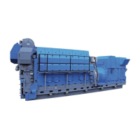
The bearing caps and bearing blocks are bolted
together by waisted bolts.
Figure 5: Connecting rod.
Crankshaft and main bearings
The crankshaft, which is a one-piece forging with
hardened bearing surfaces to achieve better wear
resistance, is suspended in underslung bearings.
The main bearings are of the trimetal type, which
are coated with a running layer. To attain a suitable
bearing pressure and vibration level the crankshaft
is provided with counterweights, which are attached
to the crankshaft by means of two hydraulic
screws.
At the flywheel end the crankshaft is fitted with a
gear wheel which, through two intermediate wheels,
drives the camshafts.
Also fitted here is a coupling flange for the connec-
tion of an alternator. At the opposite end (front end)
there is a gear wheel connection for lube oil and
water pumps.
Lubricating oil for the main bearings is supplied
through holes drilled in the engine frame. From the
main bearings the oil passes through bores in the
crankshaft to the big-end bearings and thence
through channels in the connecting rods to lubricate
the piston pins and cool the pistons.
Camshaft and camshaft drive
The inlet and exhaust valves as well as the fuel
pumps of the engine are actuated by two cam-
shafts.
Due to the two-camshaft design an optimal adjust-
ment of the gas exchange is possible without inter-
rupting the fuel injection timing. It is also possible to
adjust the fuel injection without interrupting the gas
exchange.
The two camshafts are located in the engine frame.
On the exhaust side, in a very high position, the
valve camshaft is located to allow a short and stiff
valve train and to reduce moving masses.
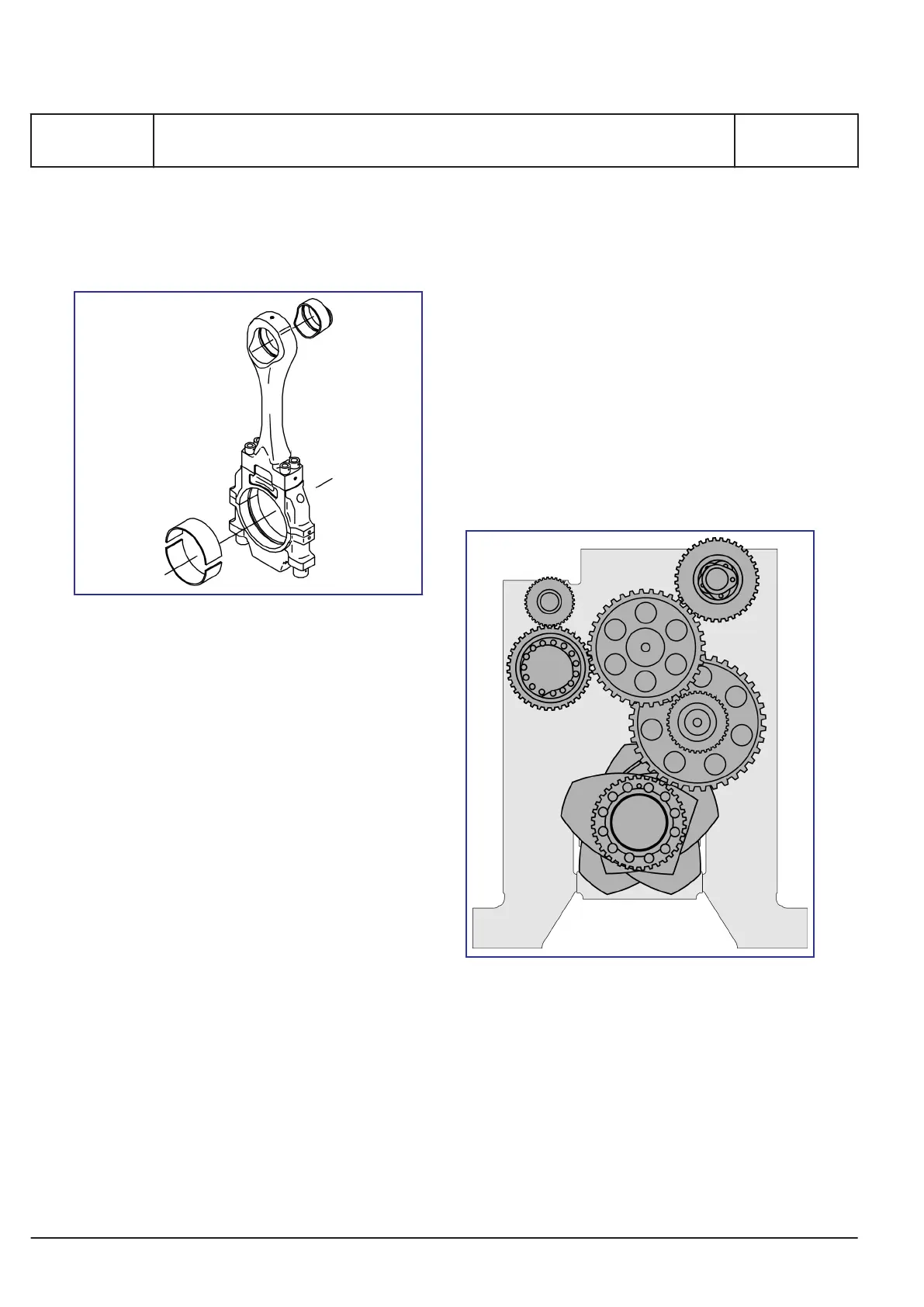
Figure 6: Twin camshafts.
The injection camshaft is located at the service side
of the engine.
Both camshafts are designed as cylinder sections
and bearing sections in such a way that disassem-
bly of single cylinder sections is possible through
the side openings in the crankcase.
The two camshafts and the governor are driven by
the main gear train which is located at the flywheel
end of the engine. They rotate with a speed which
is half that of the crankshaft.
MAN Diesel & Turbo
B 10 01 1
General description
1689477-8.1
Page 4 (7)
L27/38S, L27/38
2015.11.26
 Loading...