GROVE Published 10-21-2010, Control# 198-04 7-49
5540F/YB5515 SERVICE MANUAL TRANSMISSION AND TORQUE CONVERTER
4. Apply a small quantity of Loctite 242 to the threads in the
knurled nut 2 before fitting.
Torque Settings
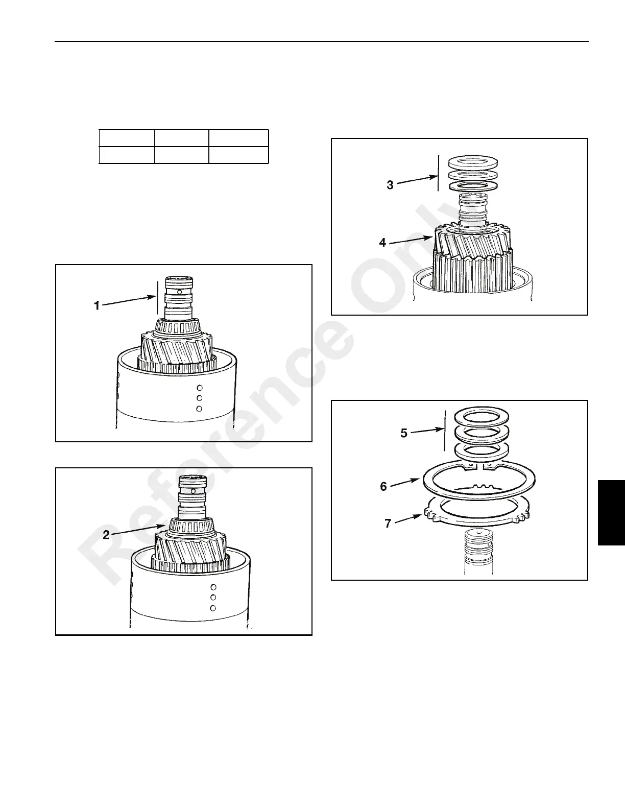
Disassembly (Figure 7-73)
1. Carefully remove piston ring seals.
NOTE: If the piston ring seals are excessively worn then
check for burrs or damage on the shaft grooves. If
necessary remove burrs with a fine grade abrasion
paper and oil.
2. Remove the taper bearing (2, Figure 7-74) using pullers.
3. Remove the thrust bearing and thrust washers
(3, Figure 7-75).
4. Withdraw the gear and splined hub assembly 4 with the
needle roller bearing and spacer. Note the position of the
spacer to ensure it is installed correctly on reassembly.
5. Remove thrust bearing and thrust washers
(5, Figure 7-76).
6. Remove the clutch friction/counter plates retaining
circlip 6.
7. Remove pressure (end) plate 7.
8. Remove the clutch friction/counter plates (8,
Figure 7-77). Keep them together in sets, DO NOT mix
the plates with those from other clutches.
9. Remove last counter plate 9.
10. Remove the disc spring 10.
Item lb ft Nm
2 8-10 10-15
Reference Only

 Loading...


