GROVE Published 10-21-2010, Control# 198-04 8-23
5540F/YB5515 SERVICE MANUAL AXLES/DRIVE SHAFTS/WHEELS AND TIRES
13. Connect the track rod and steering cylinder to the axle
steering knuckle. Tighten the track rod nut to a torque of
100 lb-ft (135 Nm), then continue to tighten to next
castellation and insert the pin.
14. Lightly oil the inner wheel bearing 6 and its cup 7. Then
install them into bearing carrier 8.
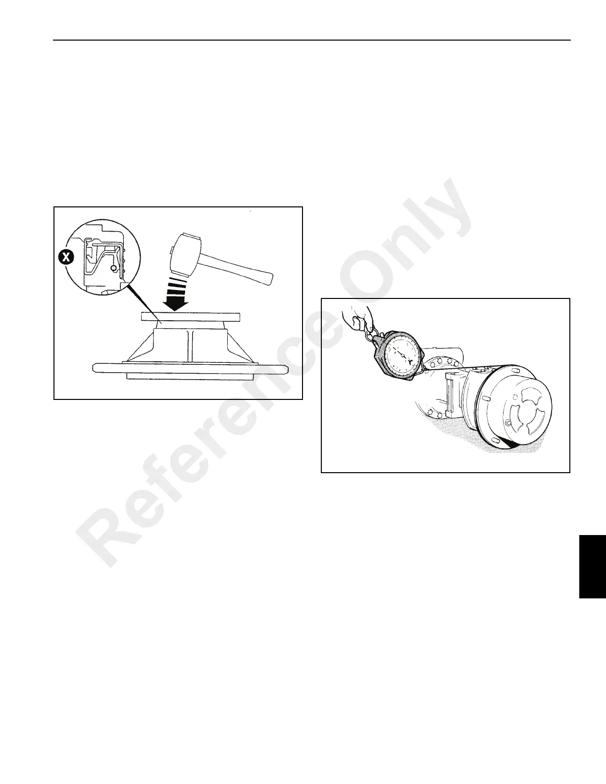
15. Install a new combination seal 9 into the bearing carrier.
Figure 8-47.
Do not lubricate before installing. Drive the seal squarely
into carrier until locating lip is flush as shown at X.
NOTE: After assembling the bearing carrier to the swivel
hub, make sure that there is sufficient clearance
between the hub and seal.
16. Install the cup 10 of outer wheel bearing 11 into the
bearing carrier 8. Grease the bore of the seal and the
surface of the stub.
17. Install the bearing carrier 8 onto hub swivel 3.
18. Install new brake seal 12 to the hub swivel.
19. Install new seals 13 and 14 into the grooves in the brake
piston 15 and annulus carrier 16.
20. Carefully press piston 15 all the way into the annulus
carrier housing.
21. Align relationship marks made on disassembly.
Assemble annulus ring 17 to annulus carrier 16 and
secure with retaining ring 18. Make sure the two
blanking plugs Z Figure 8-45 are installed to the annulus
carrier. Apply Loctite 242 to threads.
NOTE: Inspect the inside of the annulus carrier and piston
for marks. Any sign of scoring on a seal contact
surface can cause leaks.
NOTE: Make sure blanking screw Y are installed. Apply
Loctite 242 to threads.
22. Install the annulus assembly onto the splined hub.
Check that the relationship marks align. Push the
annulus assembly into the splined hub until the splines
of the annulus assembly are flush with the end of the
splined hub. Fit brake seal 19 onto the hub swivel.
23. Install retainer plate 20, making sure the breather hole
and brake galleries align. Secure using Verbus Ripp
bolts 21 and tighten until the annulus assembly just
rocks.
24.
Check the seal drag rolling force:
a. Use
a spring balance
and cord wrapped around the
planet carrier flange Figure 8-48. Pull the spring
balance so that the hub rotates. Do this several
times to set the seal and then record the reading.
b. Remove the planet gear carrier and tighten the new
Verbus Ripp bolts 21 to 122 lb-ft (166 Nm).
c. Repeat steps 24 and 24A and record the reading.
d. To get the rolling force, subtract the seal drag rolling
force (Step 24 A) from reading obtained at step 24C.
The result should be 3 to 34 lb (1,4 to 15,3 kg).
If the resulting force is outside these limits check
that seal 9 is installed correctly and or replace
bearings 6 and 11.
NOTE: A high rolling force reading may indicate the oil seal
was damaged during installation.
25. Assemble friction plates 22 and counter plates 23 onto
the carrier 16. If the original brake pack is being used,
return the plates to their original positions (see
Disassembly, step 10). Soak new friction plates in gear
oil before assembly.
26. Assemble the brake friction plate 24. Install retaining
ring 25.
27. If axle is attached to the machine, bleed the brake
system. With the engine running, gently apply the
brakes and then release them. Check that the piston
Reference Only

 Loading...


