NATIONAL CRANE Published 09-06-2019 Control # 691-01 4-23
NBT60L OPERATOR MANUAL SET-UP
REMOVABLE COUNTERWEIGHTS
The NBT60L counterweight configuration features two 3000
lb (1360.8 kg) counterweight sections.
The following procedures are applicable for mounting and
stowing the counterweights.
The counterweights can be stored on the mounting posts (1,
Figure 4-15) located on the forward part of the carrier deck.
The crane can be equipped with an optional camera system.
The rear view camera can be used to view the mounting and
stowing of the counterweights. For more information about
the optional cameras, see Camera System (Optional), page
3-35.
Refer to Figure 4-20 for an illustration of the components that
make up the counterweight.
Using the Counterweight Control Panels
Figure 4-16 shows the counterweight control panel. A control
panel is located on each side of the superstructure. The
control panels function only if the Crane Function Power
Switch is turned off, an armrest is in the up position, or there
is no one sitting in the crane cab operator’s seat. A green
LED (6, Figure 4-16) on the left side of the control panel
illuminate to indicate the control panel is operational.
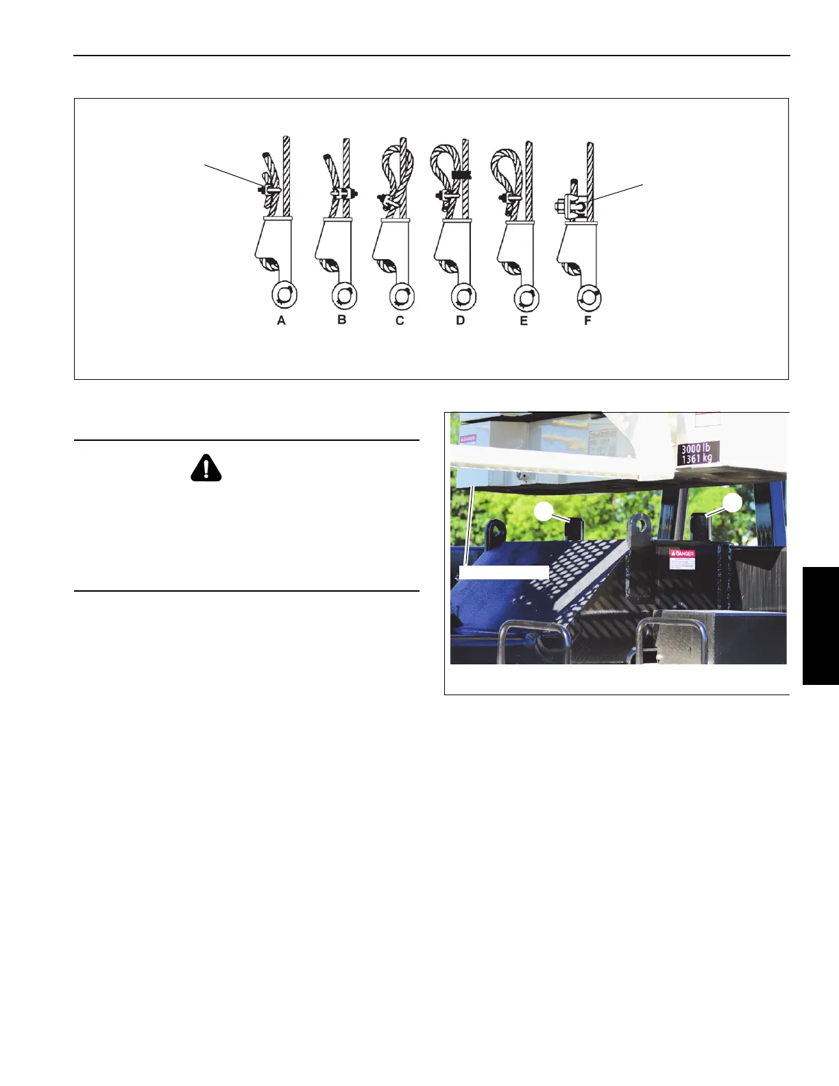
FIGURE 4-14
Wedge Socket
Specialty Clip
Specialty Wedge
DANGER
Ensure that all mounting pins are properly installed and
locked during and after operating the counterweight
removal system.
Clear all personnel from the counterweight and
superstructure area when mounting or removing the
counterweight(s).
1
FIGURE 4-15
9661
1
Counterweight

 Loading...


