SET-UP OPERATOR MANUAL NBT60L
4-24 Published 09-06-2019 Control # 691-01
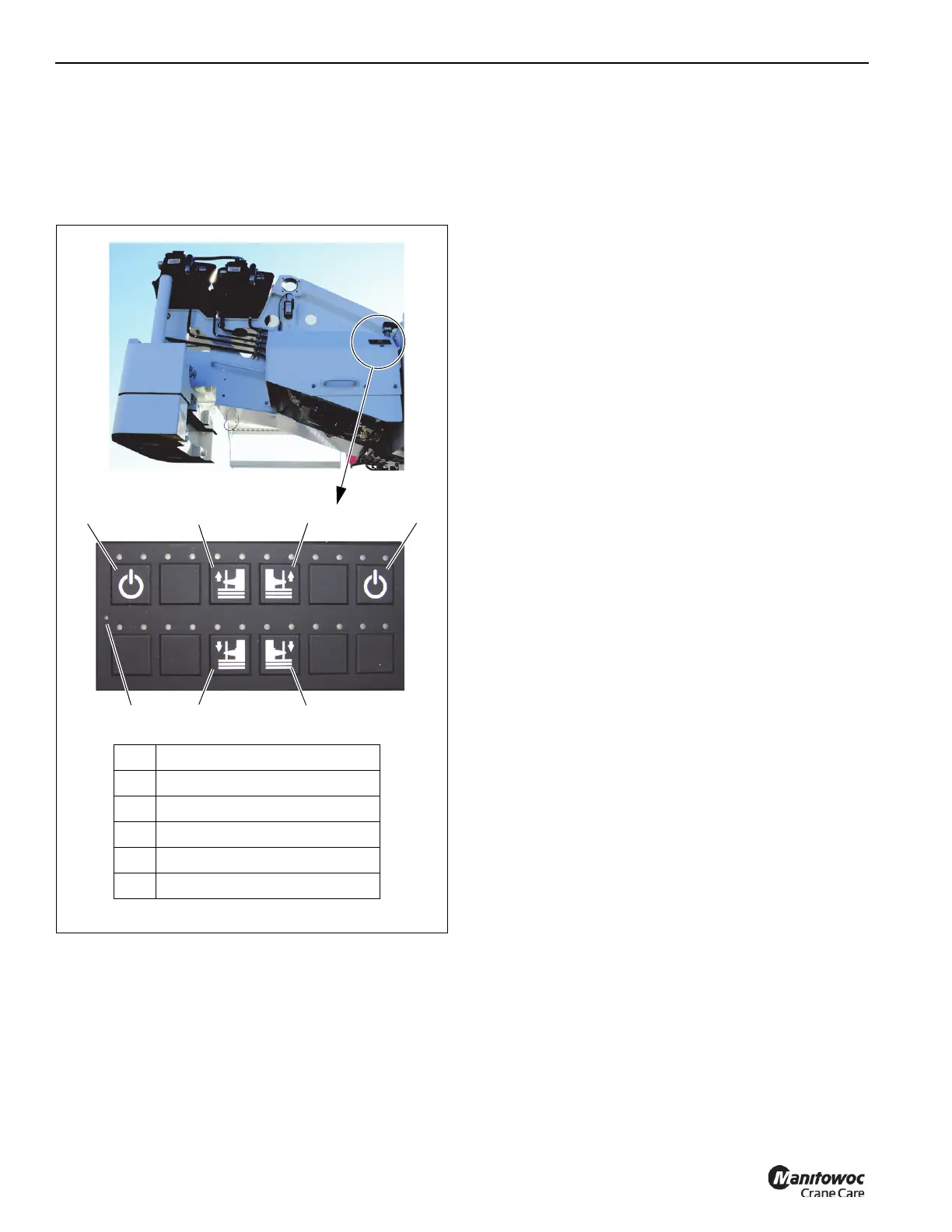
To initiate the function, press and hold the power button (1),
then the counterweight raise or lower button (4, 5,
Figure 4-16). If a counterweight removal cylinder raise or
lower button (4, 5, Figure 4-16) is pressed without first
pressing and holding a Power Button (1, Figure 4-16), a red
LED above that button will flash.
Lowering the Counterweight Cylinders
1. Press and hold a Power Button.
2. Press and hold the left and right Counterweight Removal
Cylinder Lower Buttons.
3. Release the left and right Counterweight Removal
Cylinder Lower Buttons when cylinders are at the proper
position to pin the counterweight to the cylinders.
If cylinders and counterweight do not vertically align,
return to cab and swing superstructure until alignment is
achieved.
NOTE: The cylinders can rotate axially when no
counterweight is installed, causing the cylinder pin
holes to not align with holes in counterweight. If this
occurs, rotate the cylinder rod using your hand or
counterweight pin.
Raising the Counterweight Cylinders
1. Press and hold a Power Button.
2. Press and hold the left and right Counterweight Removal
Cylinder Raise Buttons.
3. Release the left and right Counterweight Removal
Cylinder Raise Buttons when the cylinders are at the
fully raised position.
NOTE: If the counterweight hits the wear pads on the
superstructure when raising, re-align
counterweight mounting lugs, lower counterweight
back down onto mounting lugs on carrier deck to
realign counterweight on cylinder pins, then raise
counterweight again.
Mounting the Top Counterweight
Use the following procedure to install the 3000 lb (1360.8 kg)
top counterweight section (1, Figure 4-20) on a NBT60L
crane.
1. Position the crane on a firm, level surface.
2. Fully extend and set the outriggers, then level the crane
(see Setting the Outriggers, page 4-2).
3. (Optional) Set the camera display to view the rear view
camera as necessary.
4. Set display in Operator’s Console to the
RCL Operating
Mode Screen (Figure 4-17) (see Section 7, Rated
Capacity Limiter
).
FIGURE 4-16
7868-02
1 Power Buttons
2 Right Cylinder Raise Button
3 Left Cylinder Raise Button
4 Right Cylinder Lower Button
5 Left Cylinder Lower Button
6 Panel Power Indicator (LED)
12
4
3
5
6
9662
1

 Loading...


