TRANSMISSION AND TORQUE CONVERTER CD5515-2/YB5515-2 SERVICE MANUAL
7-4 Published 1-20-2017, Control# 483-02
Both the mainshaft and the layshaft assemblies have a
single clutch each. The three-position solenoid M, when
energized, directs pressurized oil to either the mainshaft
clutch or the layshaft clutch.
The 4 wheel drive unit (used on four-wheel drive cranes) has
a single clutch F. In normal operation the clutch is spring
loaded and therefore engages to give four-wheel drive. The
2/4 wheel drive solenoid N is not used on this crane.
Hydraulic Operation – Two-Wheel Drive
When the Powershift Transmission Figure 7-3 is operated,
multi-disc clutch packs are pressurized and engaged. The
engaged clutch packs then transfer drive from the engine to
the road wheels (via the torque converter A, input shaft H
and the drive shafts).
Different combinations of engaged clutches give four gear
ratios in forward and reverse drive. There must always be
two clutches engaged before the crane will drive: 1. a
direction ratio clutch (i.e., forward low) and 2. a drive clutch
(i.e., layshaft or mainshaft).
Figure 7-3 shows 1st gear reverse selected, therefore, the
two engaged clutches will be reverse low ratio clutch B and
layshaft drive clutch E.
For purpose of this description, clutches not used when 1st
gear reverse is selected are not shown.
Oil from the pump Q is fed through an internal passage by
way of the filter Y to pressure the maintaining valve R, which
maintains a constant pressure to the solenoid valve adapter
block S.
The solenoid adapter block houses the solenoid valves,
which are used to divert oil to the clutch packs.
Excess oil from the maintenance valve flows through the
casing to the torque converter. Oil enters the converter
between the converter hub and stator support, and leaves
between the stator and the input shaft. Pressure in the
converter is controlled by relief valve T which dumps oil from
the converter line back to the sump.
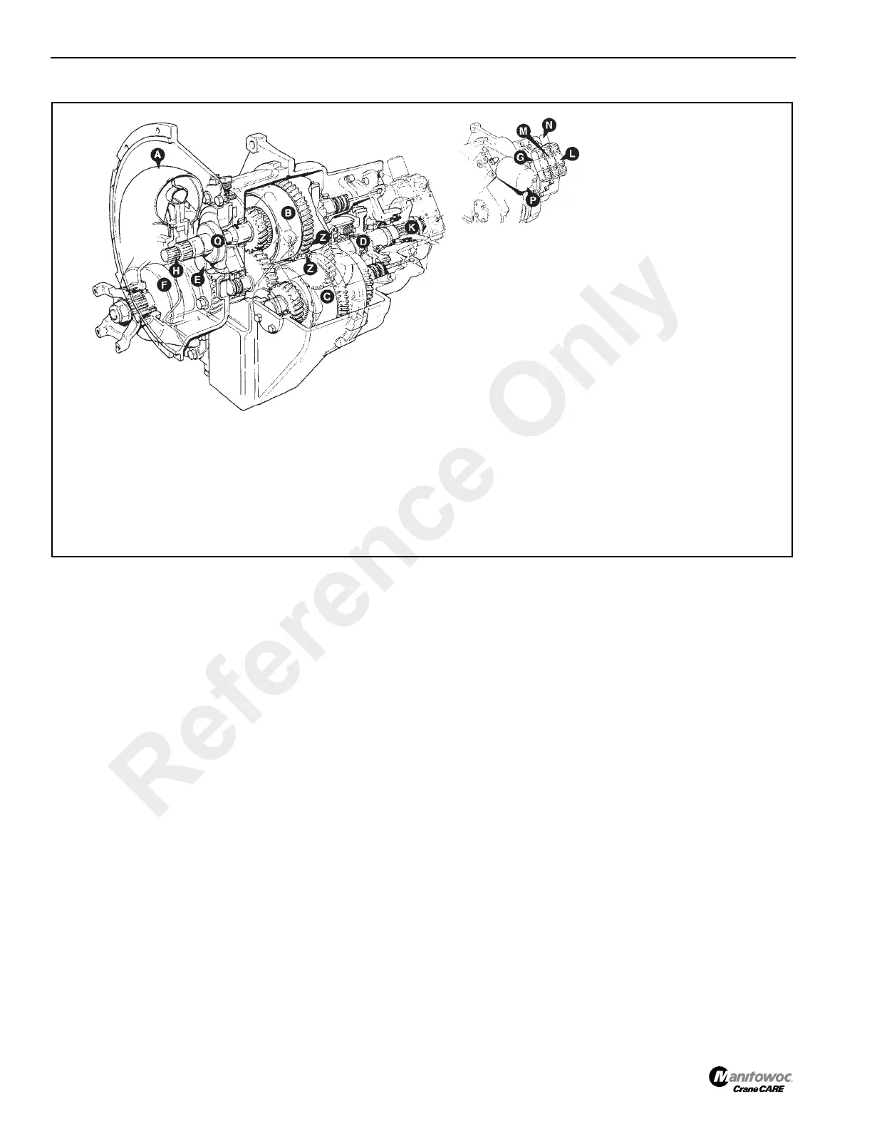
FIGURE 7-2
a0231
A - Torque Converter
B - Input Shaft Assembly
C - Forward Clutch Assembly
D - Main Shaft Assembly
E - Layshaft Assembly
F - 4 WD Clutch Assembly
G - 3 Position Solenoid Valve (Reverse)
H - Input Shaft
K - Spined Output Shaft
L - 3 Position Solenoid Valve (Forward)
M - 3- Position Solenoid Valve (Mainshaft/Layshaft
N - 2/4 Wheel Drive Solenoid (Not used)
P - Hydraulic Filter
Q - Pump
Z - Spur Gears
NOTE: The filter is not used on this
transmission. A remote filter
installation is used.
Reference Only
 Loading...


