Grove Published 1-20-2017, Control# 483-02 11-23
CD5515-2/YB5515-2 SERVICE MANUAL STRUCTURALS
Planetary Set
NOTE: See Figure 11-16 for item number identification.
1. Remove the spiral retaining rings from the planet pins.
2. Remove the pins from the carrier by carefully tapping
them out.
3. Remove the planet gears, thrust washers and bearings
from the carriers.
4. Inspect the pins, bearings, and gear bores for evidence
of wear and replace if necessary.
5. On output planet sets, note that two bearings with a
spacer between them are used.
6. Before reassembly, be sure to insert the round plates
into the carriers.
7. To re-assemble, be careful to line up the planet pins with
the thrust washers and bearings and then press the
knurled part of the pin into the carrier.
Motor
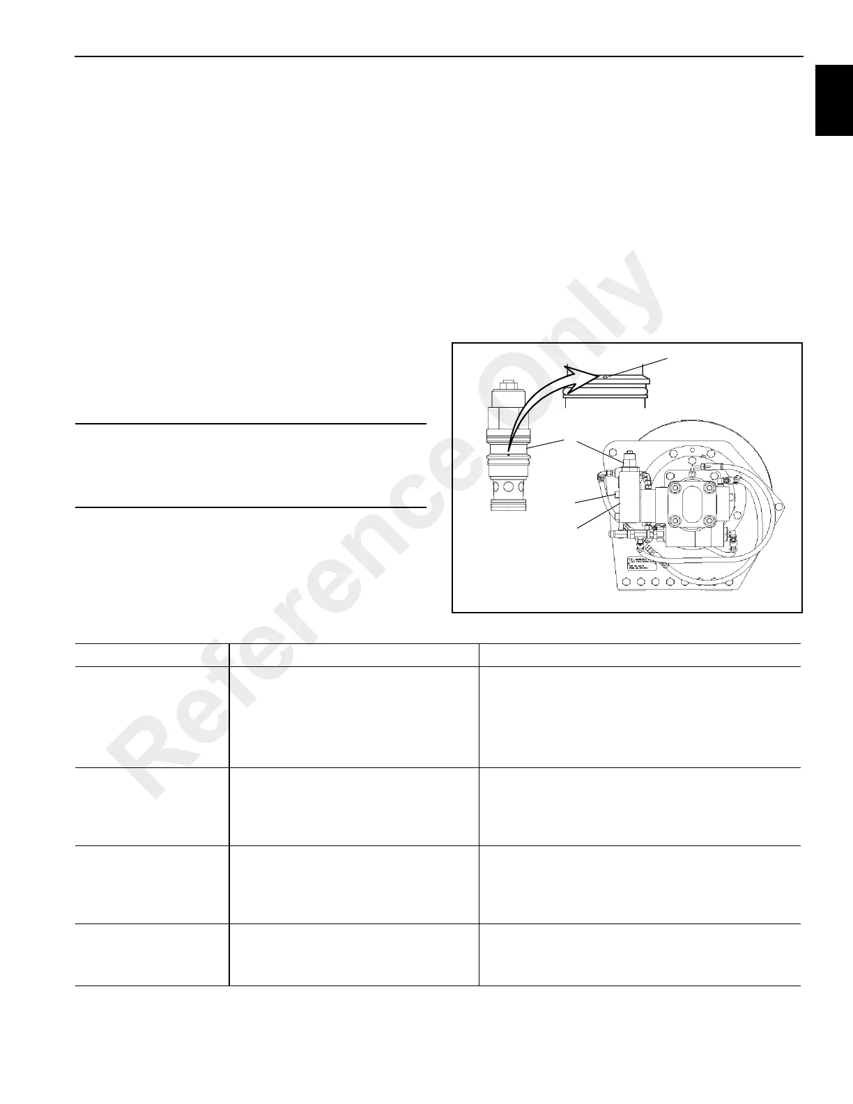
1. Remove the hose and the counterbalance block (42)
from the motor assembly.
2. To remove the counterbalance block (42), loosen and
remove the 4 capscrews (55).
3. Remove the counterbalance valve (58) from the
counterbalance block and inspect the small metering
hole located on the side of the cartridge valve to make
sure it is not obstructed (Figure 11-17). Also inspect the
O-rings to insure that they are not cut or flattened.
4. Motors and cartridge valves are not serviceable in the
field. Return them to an authorized distributor for
service.
CAUTION
Possible Equipment Damage!
If the pins are not lined up properly, the thrust washers
can be shattered during the pressing operation.
FIGURE 11-17
2
3
1
Metering Hole
7148
7147
TROUBLESHOOTING
Problem Cause Solution
Hoist does not hold
load
Excessive back pressure in the system.
Check the system for restrictions and reduce the
back pressure.
Brake discs are worn out. Replace brake discs.
Hoist clutch is slipping.
Inspect the clutch and driver for wear and replace
worn parts.
The hoist does not
raise the load it should.
Relief valve setting may be too low to
allow proper lifting.
Increase relief valve pressure setting.
Load being lifted may be more than the
hoist's rating.
Reduce the load or re-rig to increase mechanical
advantage.
The hoist does not
lower the load.
The brake valve was connected
improperly after being disconnected.
Check plumbing and connect lines properly.
The cartridge in the brake valve may
have a plugged metering hole.
Remove the cartridge and clean it if necessary.
Oil leaks from the vent
on the motor side of the
hoist.
The motor shaft seal may have failed.
Replace this seal and reduce back pressure if high
pressure caused the shaft seal to fail.
Brake piston seals may have failed. Service the brake section and replace worn parts.
Reference Only
 Loading...


