GROVE Published 1-20-2017, Control# 483-02 10-7
CD5515-2/YB5515-2 SERVICE MANUAL STEERING SYSTEM
STEERING PROXIMITY SWITCHES
General
The purpose of the steering proximity switches in the
steering system is to prevent the changing of steering modes
until all wheels are aligned forward. The sensors are
positioned on the front and rear axles Figure 10-5 and are
activated when a bracket attached to the steering yoke of the
axle, is aligned with the sensor.
Principle Of Operation
The steering system electrical circuit includes two sensors
Figure 10-7 one selector switch, one relay box and two
solenoid valves. The selector switch is controlled by the
operator in the cab to select the steering modes. The relay
box, located under the instrument panel, contains relays that
control the steering mode solenoid valves.
The system is used to select one of the three steering
modes. When the selector switch in the cab is placed in
either two-wheel steer, four-wheel steer or crab steer, that
particular mode of steering is used to steer the crane. The
system, however, will not activate unless the front and rear
wheels are in or pass over the forward position. For example,
when the front wheels are not aligned forward in two wheel
steer mode and the crane must be placed in four wheel steer,
placing the steering selector switch, located in the cab, to
four wheel steer will not place the steering system in four
wheel steer mode. Turning the front wheels to forward
position or past, activates the proximity switches and
energizes the relays in the relay box, which in turn energize
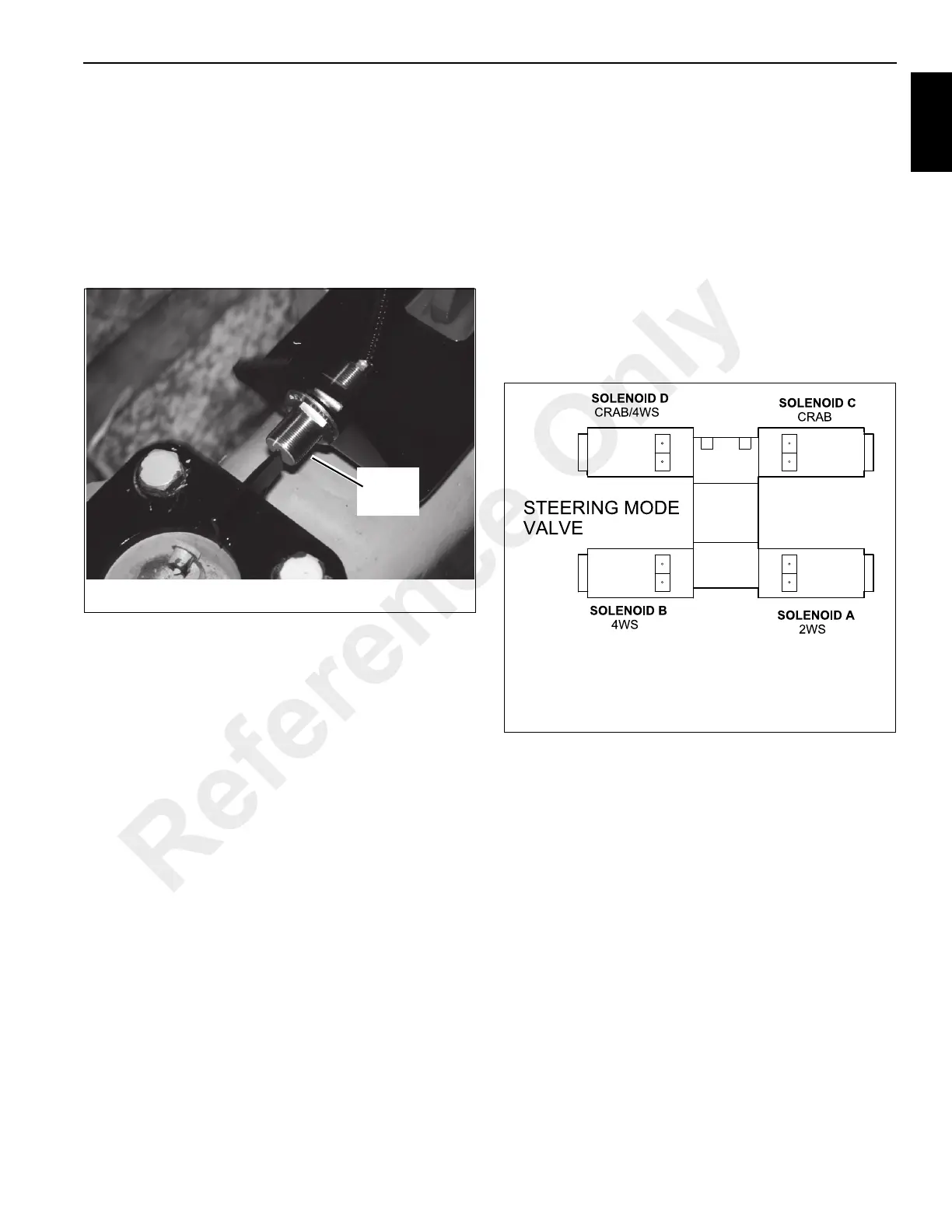
the correct solenoid arrangement Figure 10-6 to put the
steering system in four wheel steer.
FIGURE 10-5
p1875
Steering
Sensor
FIGURE 10-6
a0761
2WS = Solenoid “A” Energized
Crab = Solenoids “B & C” Energized
4WS = Solenoids “C & D” Energized
Reference Only
 Loading...


