STRUCTURALS CD5515-2/YB5515-2 SERVICE MANUAL
11-16 Published 1-20-2017, Control# 483-02
MAIN HOIST
Description
The hoist is composed of motor control valve, a fixed
displacement hydraulic motor, a multiple disc brake, and a
pair of planetary gear sets.
The multiple disc brake is spring applied and hydraulically
released through a port in the brake housing. An overrunning
clutch allows the hoist to raise the load without releasing the
brake while at the same time holding the load until there is
sufficient pressure to release the brake when hoisting down.
Maintenance
Inspect the hoist daily for oil leaks, loose bolts, and worn
hoist cable. Check the gearbox and brake oil every 500
hours. Do an oil change every 1000 hours. Refer to
Preventative Maintenance, page 5-1. Inspect the hoist from
the deck of the crane. Do not stand on the turret.
Warm-up Procedure
A warm-up procedure is recommended at each start-up and
is essential if ambient temperature is below +40°F (4°C).
Run the crane at idle with the hoist control lever in neutral
and allow sufficient time for the hydraulic system to warm up.
Operate the hoist at low speeds, forward and reverse,
several times to prime all lines with warm hydraulic oil and
circulate lubricant through the planetary gear sets.
Removal
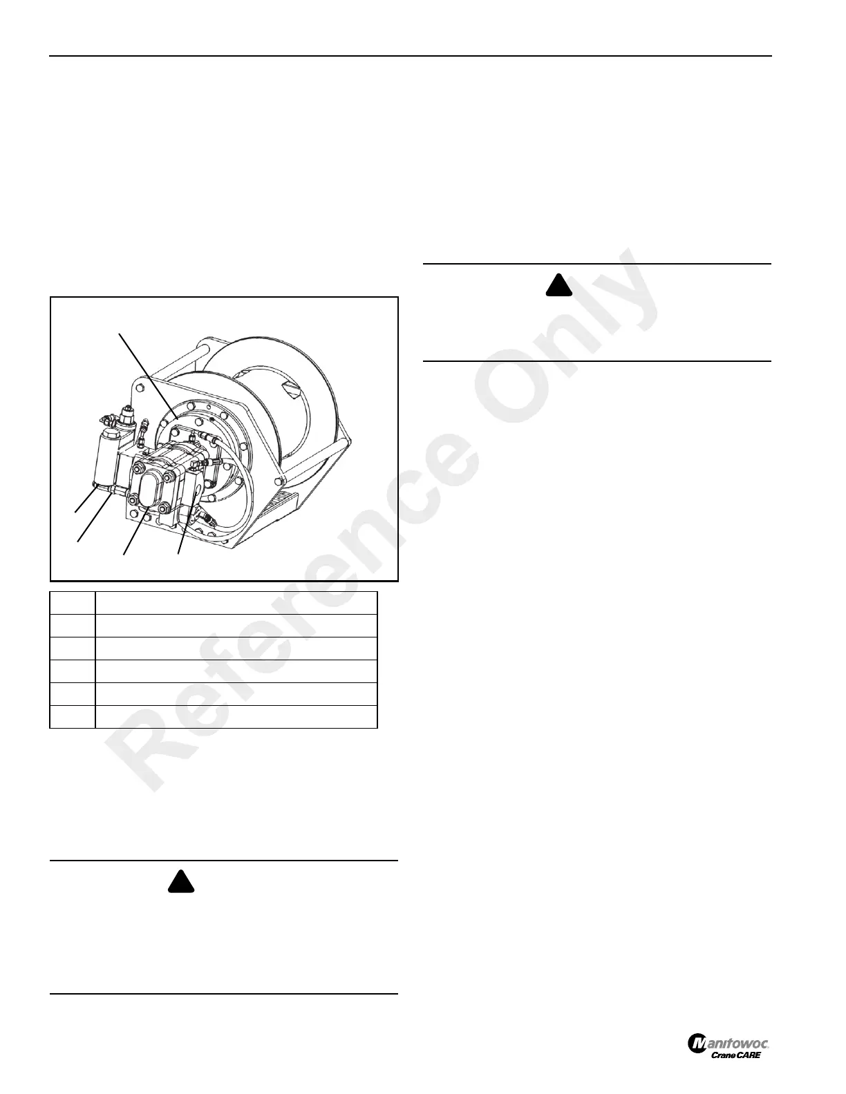
NOTE: See Figure 11-8 for item identification.
6. Remove the cable from the hoist drum.
7. Tag and disconnect the hoist hydraulic lines. Cap and
plug all hydraulic openings.
8. Attach a lifting device to the hoist and take up the slack.
9. Remove the mounting bolts from the hoist.
10. Remove the hoist from the crane with the lifting device.
Hydraulic Hoses
Inspect the hydraulic hoses and replace as required.
Hoist Installation
1. Attach a lifting device to the hoist.
2. Lift the hoist with a lifting device onto the turret.
3. Install mounting bolts and washers.
4. Remove the lifting device.
5. Reinstall the hydraulic hoses as per removal tags.
Drum Rotation Indicator
The drum rotation indicator (DRI) is located on the left side of
the hoist and transmits a rotation signal to a solenoid (thumb
thumper) located in the hoist control lever on the operator’s
control panel.
The DRI transducer may have an optional integral Last Layer
Indicator (LLI) which is programmed to notify the operator
when there are three wraps of cable left on the drum.
Removal
• Loosen the collar on the connector and unplug the DRI
cable.
• Remove the two retaining screws.
Item Component
1Brake
2 Motor
3 Case Drain
4 Pressure Port to Raise
5 Pressure Port to Lower
WARNING
Fall Hazard!
Do not, under any circumstances, work at an elevated
height without using proper fall protection as required by
local, state, or federal regulations. Death or serious injury
may result.
WARNING
Crushing Hazard!
The combined weight of the hoist and 390 ft of wire rope is
730 lbs (331 kg). Death or serious injury may result.
Reference Only
 Loading...


