GROVE Published 1-20-2017, Control# 483-02 8-7
CD5515-2/YB5515-2 SERVICE MANUAL AXLES/DRIVE SHAFTS/WHEELS AND TIRES
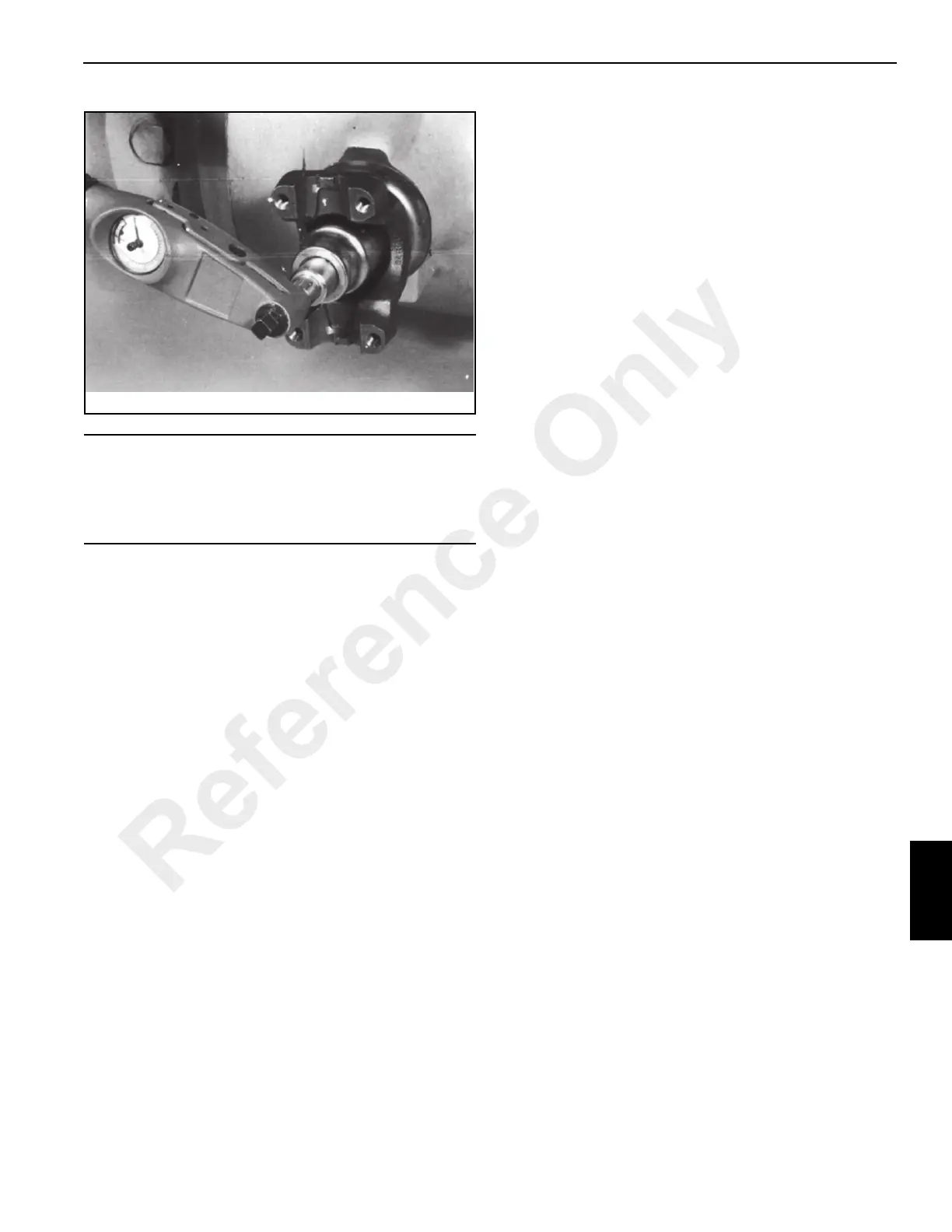
7. Stake the nut using a square ended staking tool.
Axle Hub Repair
Disassembly
NOTE: The axle does not have to be removed to
disassemble the axle hub.
1. Drain the oil from the axle hub.
2. Remove screws 24 Figure 8-8.
3. Using a soft-faced mallet, tap the planet gear carrier 18
to “crack” the joint between the carrier and the bearing
carrier 8. Then pry the planet gear carrier from the
bearing carrier. Remove and discard O-ring 23.
4. Remove a planet gear 19 only if it is defective. A planet
gear can only be replaced as an assembly, which
consists of the pinion, a bearing and two “L” shaped
retaining rings. To remove a planet gear, first remove the
retaining ring 4, then pull off the planet gear.
5. The drive shaft thrust pad 17 is drilled and taped M6 for
removal purposes. Remove the drive shaft thrust pad
from planet gear carrier.
6. Remove the external retaining ring 22 and sun gear 20.
7. Remove the Verbus Ripp bolts 16. These bolts are very
tight and care must be taken not to distort the bolt heads.
Use as short of an extension as possible. Discard the
Verbus Ripp bolts.
8. Using two metric bolts jack the annulus assembly 12, 13
& 14 off bearing carrier 8.
NOTE: Be sure annulus ring position is marked for
reassembly.
Fretting between the hub swivel and annulus
carrier mating surfaces might be evident. This
condition is normal, do not attempt to repair.
If the hub swivel and annulus carrier are to be
replaced, they must be replaced as a pair not
individually.
9. Remove internal retaining ring 14 to separate the
annulus ring 12 from the annulus carrier 13.
10. Pull off bearing carrier 8 together with the outer wheel
bearing cone 10 and cup 11. Remove combination seal
9. Remove the inner bearing cup 7 from the inboard side
of the carrier.
11. Pull off inner wheel bearing 6.
NOTE: Earlier type axles may have an O-ring and wear
ring installed in place of combination seal 9. These
parts should be discarded.
12. On later units, remove and discard combination seal 9.
13. Disconnect the track rod and steering cylinder from the
axle steering knuckles.
NOTE: If the track rod is removed completely, identify R.H.
and L.H. ends to ensure correct assembly.
The top an
d bottom trunnions are very
similar
(bottom trunnion not shown), the only difference
being that shims 28 are installed to the top trunnion
only.
14. Mark the position of the top and bottom trunnions 27,
remove bolts 26 and remove the trunnions. Retain shims
28 with top trunnion. Remove hub swivel 3.
NOTE: Trunnions may be removed easily and without
damage to the shims by pumping grease through
the grease fitting.
15. Remove top and bottom trunnion seals 29 and bearings
30.
CAUTION
If the rolling torque value (new pinion seal installed)
exceeded the reading in Step 1 by 1 Nm (0.74 lb-ft) or
more, then the collapsible spacer mounted on the axle
pinion MUST be replaced.
Reference Only
 Loading...


