GROVE Published 1-20-2017, Control# 483-02 9-17
CD5515-2/YB5515-2 SERVICE MANUAL
28. Install new seal 4 in cover 3. Be sure inside of cover is
coated with grease.
29. Install new gasket 23, cover 3, lockwashers 2 and
capscrews 1. Tighten the screws evenly in the order of
A, B, C and D Figure 9-27. When installed, tighten each
screw to a torque of 29.8 - 36.6 Nm (22-27 lb-ft).
30. Assemble the brake assembly onto the mounting
bracket 31.
31. Install the parking brake assembly onto the frame of the
crane.
32. Attach the hydraulic hose.
33. Adjust the lining clearance as described on page 9-7.
34. Open the accumulator needle valve and then bleed air
from the system as described on page 9-6.
Seal Kit Installation
The parking brake has a seal kit available. It includes all the
parts necessary to replace all the seals in the brake. These
parts are indicated in Figure 9-26 with a symbol.
NOTE: The needle valve must be in the open position for
the brake system to operate properly. If it is not
open, the charging pump will cycle every time the
brake pedal is depressed and if the crane’s engine
stops there may not be enough pressure to stop
the crane.
NOTE: When removing seals and backup rings be careful
not to scratch or mar the pistons.
The linings must be kept free of grease, oil, etc.
1. This will shut off hydraulic pressure to the parking brake.
Release system pressure by actuating the service brake
pedal until no resistance is felt. Then, engage and
disengage the parking brake to release its pressure.
2. Slowly, loosen the hydraulic hose from the parking
brake. Some pressure may still be present in the
hydraulic hose. Let the pressure escape and then
remove the hydraulic hose.
3. Cap the hydraulic hose to prevent contamination from
entering the hydraulic system.
4. Loosen lock nut 8 Figure 9-26 and back off adjusting bolt
7.
5. Remove the bolts and nuts used to fasten the brake
mounting bracket to the crane. Remove the parking
brake assembly.
6. Separate the mounting bracket 31 from the brake
assembly.
7. Clamp the brake in a vice with soft jaws with the cover 3
in a vertical position.
NOTE: Clamping should be done on sides of the brake, not
on machined surfaces.
8. Using a sharp bladed tool, carefully remove two seals 28
from housing 26. Note the direction the seals were
installed.
9. Loosen but do not remove four capscrews 1. Loosen
screws evenly in the order of A, B, C and D Figure 9-27
until spring pre-load is released.
10. Remove capscrews 1 Figure 9-26, lockwashers 2, cover
3 and gasket 23. Using a thin blade, remove seal 4 from
cover 3.
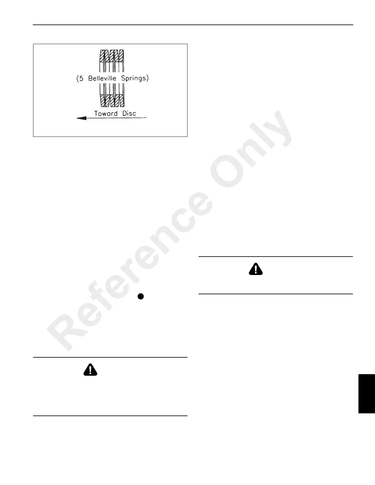
11. Remove belleville springs 5 and if present, washer 6.
When removing the belleville springs take note of the
stacking sequence.
12. Remove piston 9 from housing 26 bore. Remove O-ring
11 and backup ring 10
from piston. Push rod 12 should
also come out
with
piston 9.
13. Remove piston 15 from housing 26 bore. Remove O-
rings 13 and 16 and backup rings 14 and 17 from piston
15.
WARNING
Before replacing the parking brake seals, make sure that
the crane is on level ground. Place chocks on both sides
of the four tires. Remove the ignition key. If these
precautions are not adhered to, the crane could run you
over while performing the repair.
WARNING
Cover 3 is under spring pressure. Use care when
removing the cap to prevent personal injury.
Reference Only
 Loading...


