AXLES/DRIVE SHAFTS/WHEELS AND TIRES CD5515-2/YB5515-2 SERVICE MANUAL
8-20 Published 1-20-2017, Control# 483-02
5. Remove planet gears 28 only if defective. Note that
gears can only be removed as assemblies, which
consist of the gear, the bearing and two “L” shaped
retaining rings. To remove the planet gear, remove the
external retaining ring 29.
6. Pull off the planet gear 28.
7. The drive shaft thrust pad 26 is drilled and tapped M6 for
removal purpose. Remove the thrust pad from gear
carrier 27.
8. Remove retaining ring 31 to allow sun gear assembly 30
to be slid off the drive shaft 42.
9. Remove retaining ring 25 to allow the brake pack
assembly to be slid off the drive shaft 42.
10. Remove brake pressure plate 24, counter plates 23 and
friction plates 22.
NOTE: If the brake pack is to be reused, note the position
of the plates before removing.
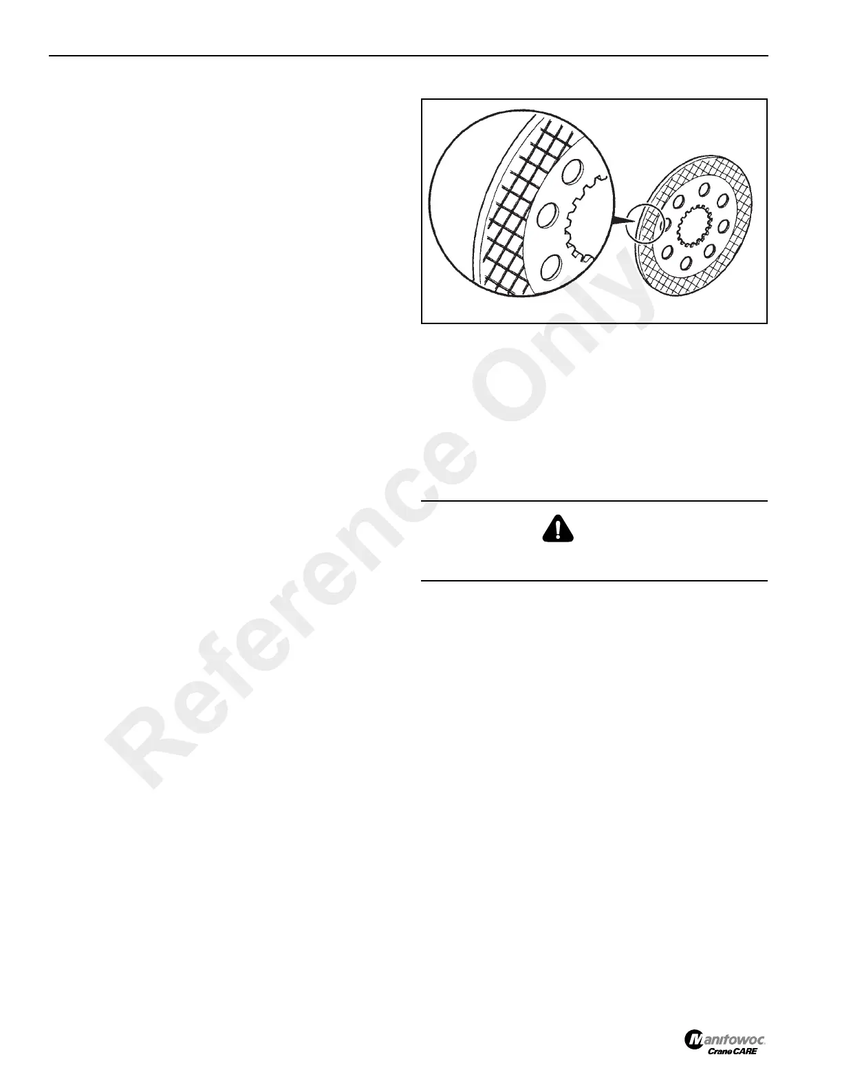
11. Examine the friction plates. Wear limit of the friction
plates is to the depth of the crosshatching Figure 8-44.
Check all plates for flatness and damage. (Some scoring
of the counter plates is normal.) Completely replace the
brake pack if it is worn or damaged. Do not replace
individual plates.
NOTE: Excessive wear of the brake and counterplates can
indicate sticking brakes or possible residual
pressure in the braking system. See Section 9,
Brakes.
12. Remove Verbus Ripp bolts 21 Figure 8-45 and retaining
plate 20. These bolts are very tight and care must be
taken not to distort the bolt heads. Use as short of
extension as possible with a six sided socket. Discard
the Verbus Rip bolts after removal.
13. Remove brake seal 19, then mark the relationship
between the annulus carrier 16, annulus ring 17 and the
hub swivel. Remove the annulus carrier with the annulus
ring from the hub swivel.
14. Remove retaining ring 18 to separate the annulus ring
from the annulus carrier. Remove brake seal 12 from the
hub swivel.
CAUTION
Do NOT reuse Verbus Ripp bolts. They must be replaced
throughout the assembly.
Reference Only
 Loading...


