GROVE Published 1-20-2017, Control# 483-02 4-29
CD5515-2/YB5515-2 SERVICE MANUAL HYDRAULIC SYSTEM
21. Install capscrews (19) and seal washers (18) in end cap
(17). Tighten the capscrews to 7.4 Nm (40 lb-in). Make
sure the seal washers are properly seated. Then, tighten
the capscrews to a torque of 27-28 Nm (235-250 lb-in) in
the sequence shown Figure 4-23.
Installation
1. Place a new gasket on the face of the swing motor
mounting flange.
2. Align the splines of the swing motor shaft with the
splines of the worm gear shaft of the swing gear box.
Install the swing motor to the gearbox with two socket
head capscrews and lockwashers.
3. Connect the hydraulic lines and fittings to the swing
motor.
4. Start the engine and slowly rotate the mast to remove
any air in the swing hydraulic circuit. Check for leaks.
Hoist Motor
Removal
1. Shut off the engine, set the parking brake.
2. Before disconnecting the hydraulic lines, clean the port
area of the hoist motor thoroughly. Disconnect the
hydraulic lines from the hoist motor. Put caps and plugs
on the hoses and ports to keep dirt out.
3. Loosen and remove the two capscrews and
lockwashers securing the motor to the hoist. Remove
the hoist motor and gasket. Discard the gasket.
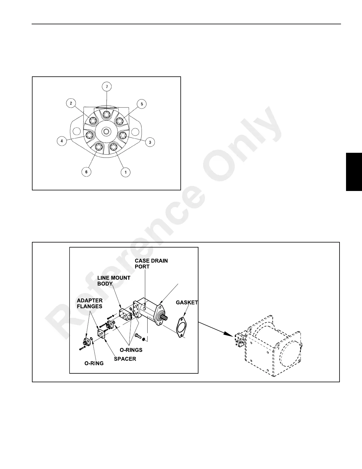
4. Remove hoses, fittings, the adapter flanges, spacer
block and line mount body Figure 4-24 from the pump.
Discard all O-rings.
Disassembly
The hoist motor is not field serviceable. It must either be
replaced or returned to your distributor for repair.
Installation
1. Install the line mount body Figure 4-24, spacer and
adapter flanges to the hoist motor. Be sure to use new
O-ring seals.
2. Install the hoist motor and new gasket to the hoist using
two capscrews and lockwashers.
a0980
FIGURE 4-24
HOIST MOTOR
Reference Only
 Loading...


