1-10
COMP
N1
COMP
N
N
L
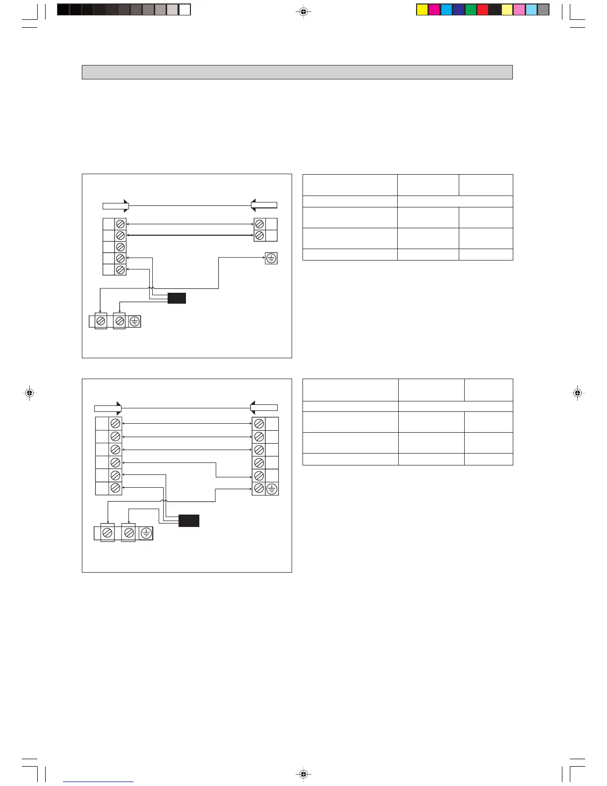
ELECTRICAL WIRING CONNECTION
Cooling Unit
IMPORTANT : * The figures shown in the table are for information purpose only. They should be checked and selected
to comply with the local/national codes of regulations. This is also subject to the type of
installation and conductors used.
** The appropriate voltage range should be checked with label data on the unit.
*** Outdoor coil sensor connection is applicable for WM09/15J and 5WM10/15J cooling unit.
!
There must be a double pole switch
with a minimum 3mm contact gap and
fuse/circuit breaker as recommended in
the fixed installation circuit.
Outdoor Unit
Terminal Block
Indoor Unit
Terminal Block
Power Supply Cable
Outdoor coil sensor connection wire
(8m long) attached in the indoor unit
COMP
N1
OF
4WV
N
L
COMP
OF
4WV
N
Heat Pump Unit (single phase)
Outdoor Unit
Terminal Block
Indoor Unit
Terminal Block
There must be a double pole switch
with a minimum 3mm contact gap and
fuse/circuit breaker as recommended
in the fixed installation circuit.
!
Power Supply Cable
Cooling Unit (single phase)
• All wires must be firmly connected.
• All wires must not touch the refrigerant piping, compressor or any moving parts of the fan motor.
• The connecting wires between the indoor unit and the outdoor unit must be clamped on the wire clamps.
• The power supply cord must be equivalent to H05RN-F (245IEC57) which is the minimum requirement.
***
Outdoor coil sensor connection wire
(8m long) attached in the indoor unit
Model (5)WM09/10/15J WM20/25J
(5)SL09/10/15C SL20/25C
Voltage range** 220V-240V/1Ph/50Hz +
!
Power supply cable size* mm
2
1.5 2.5
Number of wire 33
Interconnection cable size* mm
2
1.5 2.5
Number of wire 33
Recommended fuse A 15 20
Model (5)WM09/10/15JR WM20/25JR
(5)SL09/10/15CR SL20/25CR
Voltage range** 220V-240V/1Ph/50Hz +
!
Power supply cable size* mm
2
1.5 2.5
Number of wire 33
Interconnection cable size* mm
2
1.5 2.5
Number of wire 33
Recommended fuse A 15 20
1 IM-WMJ-1207(2)_EN 11/20/09, 4:32 PM10
 Loading...