14
Pellerin Milnor Corporation
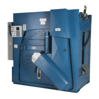
3.7.1.2 The Machine Status Area (B)
BNCLJO07.C05 0000187329 A.10 C.5 F.2 9/11/20 10:31 AM Released
This area displays the current and desired water level and temperature for the step in progress, the
current cylinder motion, and the current state of each valve.
Figure 10. The Machine Status Area
Legend
C...Chemical signals and chemical
flush valve. Numbers 1–8 indicate
a chemical is being injected. F indi-
cates a chemical flush is occurring.
Cm..Cylinder motion
Cs..Cylinder speed, in rotations per mi-
nute. Displays “RS” during Rin-
Save
®
extract deceleration.
D...Date and time
Dr..Drain indicators
Lc..Current level (percentage)
Ld..Desired level
M...Current machine status area
P...Formula progress bar
S...Steam and cooldown indicators
Sn..Step name
Tc..Current temperature
Td..Desired temperature
W...Water valve indicators
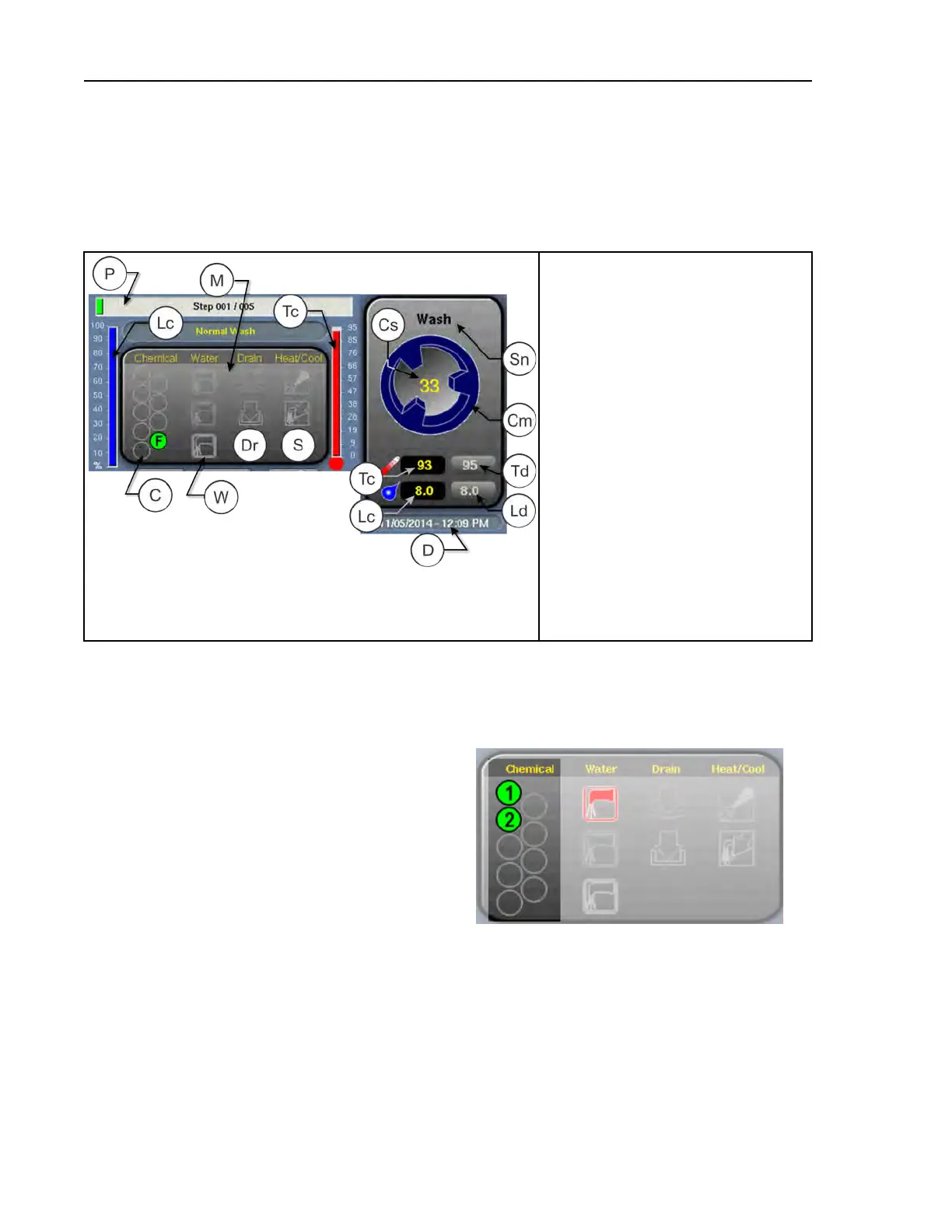
3.7.1.2.1 How to Monitor Automatic Liquid-Chemical Injections
BNCLJO11.C04 0000214843 A.10 C.5 C.2 9/11/20 10:33 AM Released
Figure 11. Chemicals from Valves 1 and 2
Injecting
If your machine controls a pumped chemical sys-
tem, the controller automatically injects chemi-
cals from the pump system while the formula
runs.
You can monitor automatic liquid-chemical in-
jections in the Machine Status area. As the con-
troller injects a chemical into the machine, the
chemical’s valve number illuminates, as shown
in Figure 11 , until the programmed injection
time expires.
3.7.1.3 Manual Control and Diagnostics Area (C)
BNCLJO11.C03 0000213316 A.10 C.5 C.3 9/11/20 10:35 AM Released
Use these buttons as explained in the following figure.
Normal Operation
17
 Loading...