Home
Mindray
Medical Equipment
BeneView T6
Mindray BeneView T6 Service Manual
5
of 1
of 1 rating
234 pages
Give review
Manual
Specs
To Next Page
To Next Page
To Previous Page
To Previous Page
Loading...
6-3
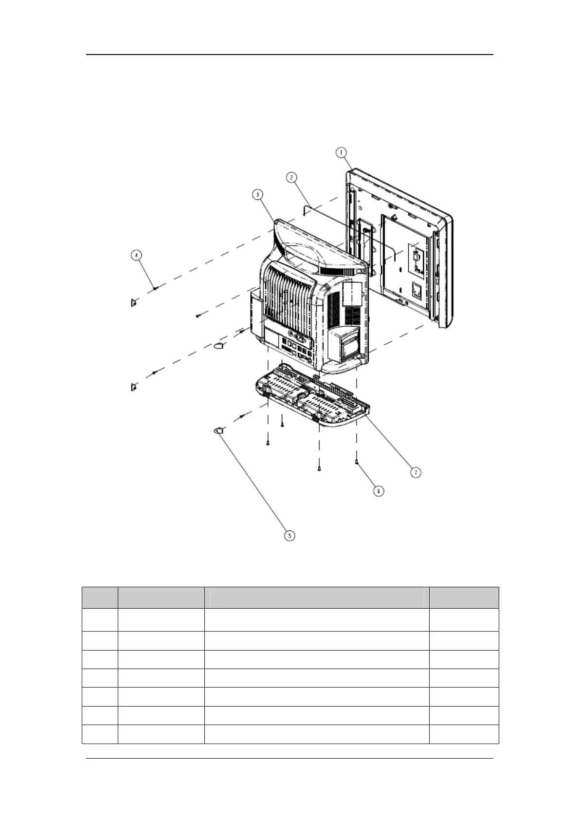
6.3 Main Unit (T9)
Exploded View
Parts List
SN
P/N
Description
Qty
1
1
15-022476-00
Front housing assem
bly (T9)
1
2
M6G-020015---
Hose, 0.47 m
1
3
68
00-30-50637
Rear hous
ing assembly
1
4
M04-
004017---
Crosshead screw M3×12
5
5
04
3-004044-00
Screw cap
4
6
M04-
005405---
Crosshead screw
4
7
68
00-30-50468
Base assem
bly
1
168
170
Table of Contents
Default Chapter
7
Table of Contents
7
1 Safety
13
Safety Information
13
Danger
14
Warnings
14
Cautions
14
Notes
15
Equipment Symbols
15
2 Theory of Operation
17
Introduction
17
System Connections
18
Mounting the Patient Monitor
18
Connectors for Peripheral Devices
19
Main Unit
20
Input System
21
Output System
22
Processing and Communications System
23
Power Management System
25
Equipment Interface System
29
Parameter Module
31
Module Infrared Communication Board
31
Module Power Board
31
Parameter Board
31
Satellite Module Rack
32
Benelink Module
33
3 Testing and Maintenance
35
Introduction
35
Test Equipment
35
Test Report
35
Preventative Maintenance
36
Recommended Frequency
36
Preventative Maintenance Procedures
38
Visual Inspection
38
NIBP Tests
39
Sidestream and Microstream CO 2 Module Tests
41
AG Tests
44
Preventative Maintenance Test Report
48
Power on Test
50
Module Performance Tests
50
ECG Tests
50
Resp Performance Test
51
Spo 2 Test
52
NIBP Tests
52
Temp Test
52
IBP Tests
53
Test
55
Mainstream CO Tests
55
Sidestream and Microstream CO
57
Module Tests
57
AG Tests
57
ICG Test
57
BIS Test
58
RM Test
59
Cco/Svo 2 Tests
60
Picco Tests
61
Scvo Tests
64
NMT Tests
65
EEG Tests
67
Nurse Call Relay Performance Test
68
Analog Output Performance Test
68
Electrical Safety Test
68
Touchscreen Calibration
69
Recorder Check
69
Network Print Test
69
Equipment Connection and Setup
70
Print Function Test
70
Benelink Module Check
71
Device Connection and Setup
71
Device Integration Function Test
73
Installation and Test Report
77
Battery Check
78
Iview System Maintenance(for T8 and T9 Monitors Only)
79
Making USB Startup Disk
79
Restoring the System
81
Setting Automatic Login
87
Factory Maintenance
88
Accessing Factory Maintenance Menu
88
Drawing Waves
88
Recorder
88
Software Version
89
Monitor Information
89
4 Troubleshooting
95
Introduction
95
Part Replacement
95
Patient Monitor Status Check
95
Software Version Check
96
Technical Alarm Check
96
Troubleshooting Guide
96
Power On/Off Failures
96
Display Failures
97
Module Rack Failures
98
Alarm Problems
100
Button and Knob Failures
101
Recorder Failures
101
Interface Failures
102
CF Card Problems
103
Power Supply Failures
103
Network Related Problems
105
Software Upgrade Problems
106
Technical Alarm Messages
106
M51A Self Test Information
106
Device Integration Failures
107
5 Repair and Disassembly
109
Tools
109
Preparations for Disassembly
109
Basic Disassembly
110
Disconnecting the Base
110
Separating the Front and Rear Half of the Monitor
112
Further Disassembly
115
Removing the Power Switch & LED Board
115
Disconnecting the Encoder Assembly
116
Removing the Button Board
116
Removing the Touchscreen Control Board
117
Removing the Inverter of T6 and T8
118
Removing the Backlight Board of T9
119
Removing the LCD Screen
120
Removing the Alarm Lamp Board
122
Removing the Wireless AP
123
Removing the CF Assembly
125
Removing the Main Board
126
Removing the Fan
128
Removing the Speaker
128
Removing the Interface Board Assembly
129
Removing the Iview Assembly (for T8 and T9 Monitor Only)
130
Removing the Power Supply Assembly
133
Removing the Integral Module Rack
136
Removing the Recorder
141
Removing the SMR Assembly
146
Disassembling Modules
150
Disassembling the ICG Module
150
Disassembling CO Module
154
Disassembling the Benelink Module
160
Disassembling the New MPM Module
163
6 Parts
167
Introduction
167
Main Unit
168
Main Unit (T9)
169
Base Assembly
170
Front Housing Assembly
171
17" LCD with Anti-Glare Screen
171
15" LCD with Anti-Glare Screen
173
19" LCD Touchscreen
175
17" LCD Touchscreen
177
15" LCD Touchscreen
179
Rear Housing Assembly
181
Power Module
183
Integral Module Rack
184
Interface Board Assembly
185
Main Support Assembly (T8/T9)
187
Main Support Assembly (T6)
188
Main Control Board Assembly
189
6800 Wireless AP Kit (ASUS)
190
Others
191
SMR Assembly
192
SMR Inside Assembly
194
Parameter Modules
195
MPM Module
195
New MPM Module
197
Remote Display Box
199
New Wireless AP Package for 6800/6802
201
Replaceable Parts
202
Main Unit
202
Smr
204
Parameter Modules
205
Cables
206
7 Upgrade
209
Introduction
209
Upgrading Parameter Modules
210
Upgrading Functional Assemblies
212
Upgrading SMR
212
Upgrading Wireless Network Function
212
Upgrading Recorder
213
Upgrading Analog Output
213
Upgrading Iview System
213
Upgrading Software
214
How to Upgrade Software
216
A Electrical Safety Inspection
219
Power Cord Plug
219
Device Enclosure and Accessories
220
Visual Inspection
220
Contextual Inspection
220
Device Labeling
220
Protective Earth Resistance
220
Earth Leakage Test
222
Patient Leakage Current
224
Mains on Applied Part Leakage
225
Patient Auxiliary Current
227
Scheduled Electrical Safety Inspection
229
Electrical Safety Inspection after Repair
230
Other manuals for Mindray BeneView T6
Quick Guide
20 pages
5
Based on 1 rating
Ask a question
Give review
Questions and Answers:
Need help?
Do you have a question about the Mindray BeneView T6 and is the answer not in the manual?
Ask a question
Mindray BeneView T6 Specifications
General
Brand
Mindray
Model
BeneView T6
Category
Medical Equipment
Language
English
Related product manuals
Mindray BeneView T1
286 pages
Mindray DC-T6
347 pages
Mindray BeneVision N1
306 pages
Mindray BeneVision N17
123 pages
Mindray BeneVision N15
123 pages
Mindray BeneVision N12
123 pages
Mindray BeneVision TD60
28 pages
Mindray BeneVision N Series
528 pages
Mindray BeneHeart D3
208 pages
Mindray BeneHeart D30
100 pages
Mindray BeneFusion VP3 Vet
92 pages
Mindray BeneHeart C Series
78 pages

 Loading...