Front Panel Indicators, Controls, and Operation
3
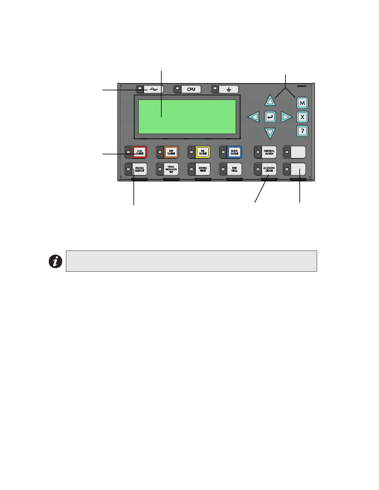
Front Panel Indicators and Control Locations (New DS Display)
Figure 2 Front Panel Indicators (New DS Display)
LED indicators are amber (trouble or supervisory), red (alarm), or green (AC On), and may
illuminate continuously (steady) or at one of two flash rates:
• Fast flash: 120 flashes per minute, 50% duty cycle
• Trouble flash: 20 flashes per minute, 50% duty cycle
Paper Labels for Buttons and Indicators
Buttons and indicators are supplied with paper labels. These labels slide into the plastic label
templates on the face of the panel. Paper labels allow for easy English / French selection and
custom-printed zone information.
Note: The General Alarm LED and pushbutton, and the Acknowledge LED and
pushbutton, are active only on a system configured for two stages.
MCG Network
Fire Control System
- System Normal -
Mar 04, 2014 12:00:00
LCD Display - four lines,
20 characters per line
Cursor buttons, ENTER, MENU,
CANCEL, INFO
Queue controls and
indicators for Alarm,
Supervisory, Trouble,
and Building
Indicators for AC On,
CPU Fault, and
Ground Fault
Controls & Indicators for Signal
Silence, Visual Indicator Test,
System Reset, Fire Drill
Two configurable
switches & amber
LEDs
Controls & Indicators for General
Alarm & Acknowledge (2 stage
systems)

 Loading...


