122
System Checkout
10.2.1 Troubleshooting using LEDs
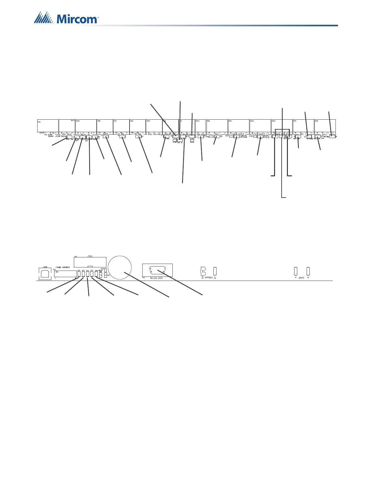
The QX-mini board uses LEDs to indicate activity and trouble events. The following
procedures allow the operator to quickly diagnose board health or eliminate the most common
system issues.
Figure 72 QX-mini board LEDs
1. For Common Trouble, look at QX-mini Main Display for indication of
•AC Power
• Ground Fault
•CPU Fail
• Zone(s) Trouble
2. Examine QX-mini board for Trouble LEDs.
3. Examine QX-mini board for COMMS LEDs.
4. Check QX-mini Main Display Connection (no dedicated LED).
5. Confirm Configurator Software matches Hardware configuration (i.e. missing amplifier
board).
6. Check Panel Address DIP Switch settings.
Trouble
Buzzer
Power
CPU
FAIL
Battery
Trouble
Ground
Fault
Main Mic
Trouble
Remote Mic
Trouble
Relay 1
Trouble
Relay 2
Trouble
Relay 1
Active
Relay 2
Active
Alarm
AC
Trouble
Common
Trouble
RS485 OUT
Trouble
RS485 IN
Trouble
RS485 OUT
Receiving
CPU
Transmiting
RS485 IN
Receiving
Aux 24V
SLC
Synch
Input 1
Synch
Input 2
Synch
Output
NAC 1
ON
NAC 2
ON
NAC 1
Trouble
NAC 2
Trouble
For (Future
Use)
OUTPUT 1
OUTPUT 2
Synch Output
Trouble

 Loading...


