80
Wiring
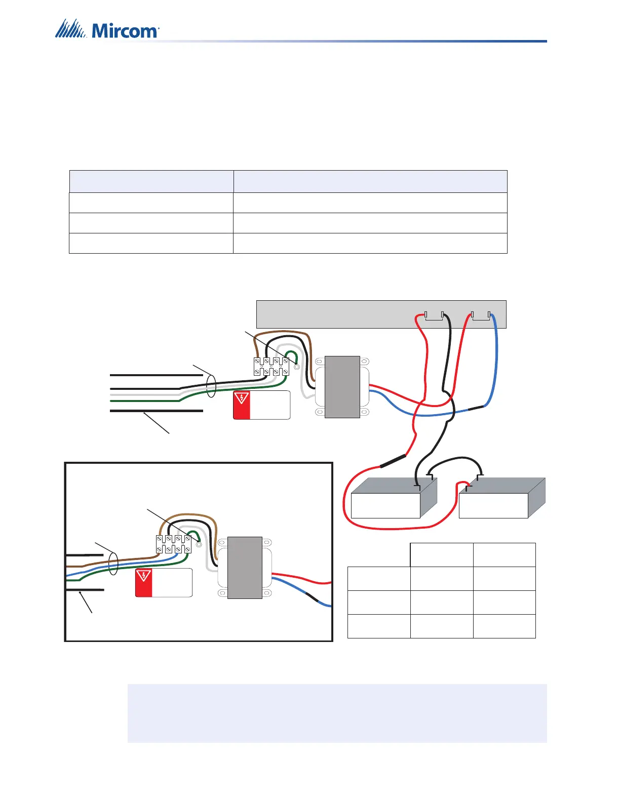
4.6 Power Supply Connections
The power supply is pre-installed as part of the Main Chassis. The following table displays the
electrical ratings. Figure 54 shows the proper connections to wire the Power Supply
successfully. There is no separate charger for the Secondary Power Connection - batteries.
Figure 54 Power supply connections
Table 14 Power Supply Electrical Ratings
Terminal Description
Electrical input ratings 120 VAC, 60 Hz, 2 A / 240 VAC, 50 Hz, 1A
Power supply total current 9.5 A maximum
Battery Fuse Replace with WX-058 Battery Cable Assembly
Attention: DO NOT exceed power supply ratings. Wire as shown.
Connect batteries after the system main A.C. power is turned on to reduce
sparking.
P4P3
BATTERY
+
+
_
_
Battery Battery
black
green
white with
blue stripe
brown
red
blue
black
green
white
EARTH
GROUND
LUG
120 VAC
To AC Input
WX-058 Cable Assembly
240 VAC 50Hz
120 VAC 60Hz
N
GND
P1 P2
red
black
black
QX-mini/QX-mini-BP MAIN BOARD
AC
No Polarity
120VAC Installation
-+
green
brown
green / yellow
blue
240 VAC
To AC Input
240 VAC 50Hz
120 VAC 60Hz
N
GND
240VAC Installation
EARTH
GROUND
LUG
AC Conduit
AC Conduit
Transformer
Signal
240V
Yeo Heung
120V
Neutral
Yellow wire
Red wire
Black wire
Black wire
Brown wire
White with
blue strip wire
Transformer

 Loading...


