66
Wiring
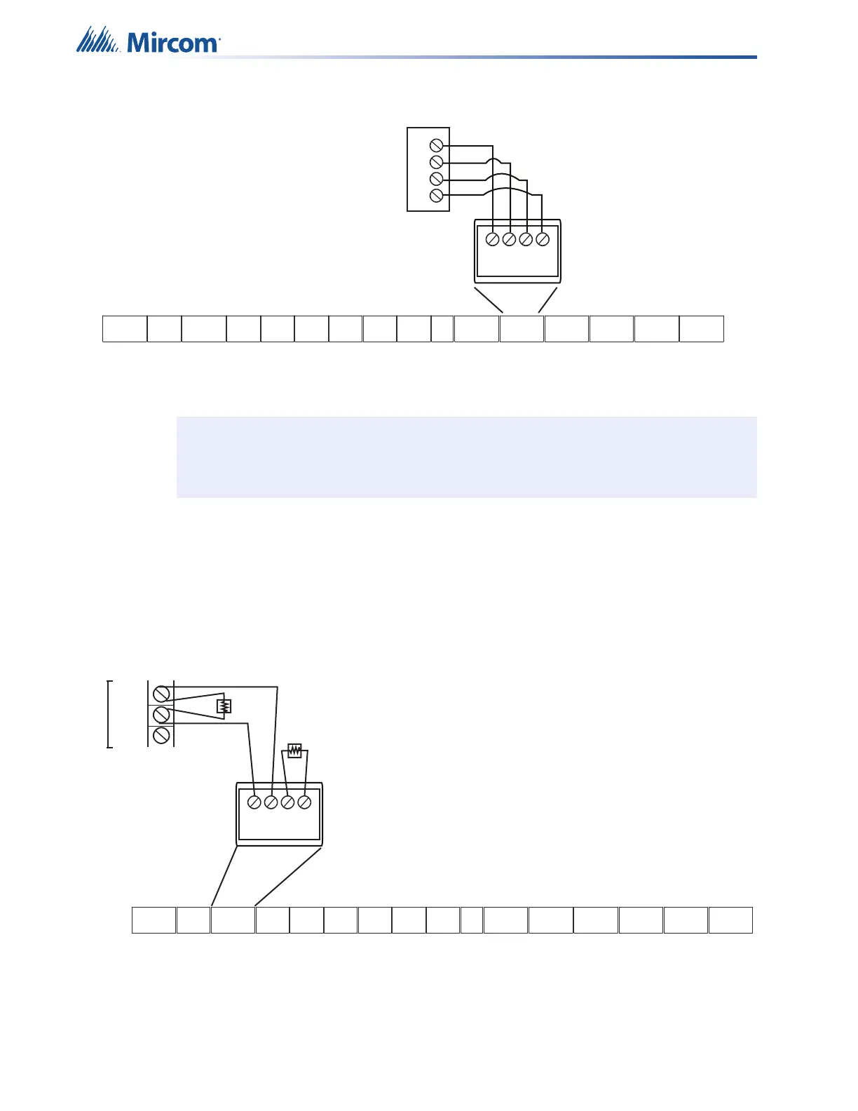
4.2.4 Synchronized Input from FACP Wiring- Class A
Figure 35 Synchronized input from FACP wiring - Class A
Sample setups:
• one QX-mini panel (generating synchronization) and three QX-mini-BP units
• one QX-mini panel and a FACP (regenerating synchronization from FACP) and two QX-
mini-BP units
• one QX-mini-BP unit (generating synchronization) and three QX-mini-BP units
4.2.5 FACP Relay Activation - Single Stage
Figure 36 FACP relay activation - single stage
Note: The inter-panel synchronization supports up to a total of four units.
SYNCH SIGNAL FROM FACP
-
+ +
-
SYNCH INPUT1
NAC CIRCUIT
FROM FACP
-
+
+
-
TS2TS16
TS10
TS5TS4TS3
TS17
TS6
TS1TS14
TS9
TS11
TS12 TS13 TS7TS8
AUX
AUDIO
RMIC
AUDIO
RELAY
IN
ALARM
AC
TBL
COM
TBL
RMIC
RS-485
RS-485 RS-485
INOUT
AUX
24V
SLC
SYNCH
SYNCH SYNCH
INPUT 2
INPUT 1
OUTPUT
NAC 1NAC 2
+OUT-
+IN-
+ 1 -
+ 2 -
+ 1 -
+ 2 -
+
S
-
+S
-
+S
-
+S
-
NO
NC
C
NO NC
C
NO
NC
C
+
-
+
-
+++
+
+
+
+
++
---
-
-
-
-
--
+2-
Relay In
1st Stage
FACP
ALARM
RELAY
COM
EOL-392
+1-
NO
NC
RELAY SIGNAL FROM FACP - One Stage
TS2TS16
TS10
TS5TS4TS3
TS17
TS6
TS1TS14
TS9
TS11
TS12 TS13 TS7TS8
AUX
AUDIO
RMIC
AUDIO
RELAY
IN
ALARM
AC
TBL
COM
TBL
RMIC
RS-485
RS-485 RS-485
INOUT
AUX
24V
SLC
SYNCH
SYNCH SYNCH
INPUT 2
INPUT 1
OUTPUT
NAC 1NAC 2
+OUT-
+IN-
+ 1 -
+ 2 -
+ 1 -
+ 2 -
+
S
-
+S
-
+S
-
+S
-
NO
NC
C
NO NC
C
NO
NC
C
+
-
+
-
+++
+
+
+
+
++
---
-
-
-
-
--
EOL-392

 Loading...


