92
Indicators & Controls
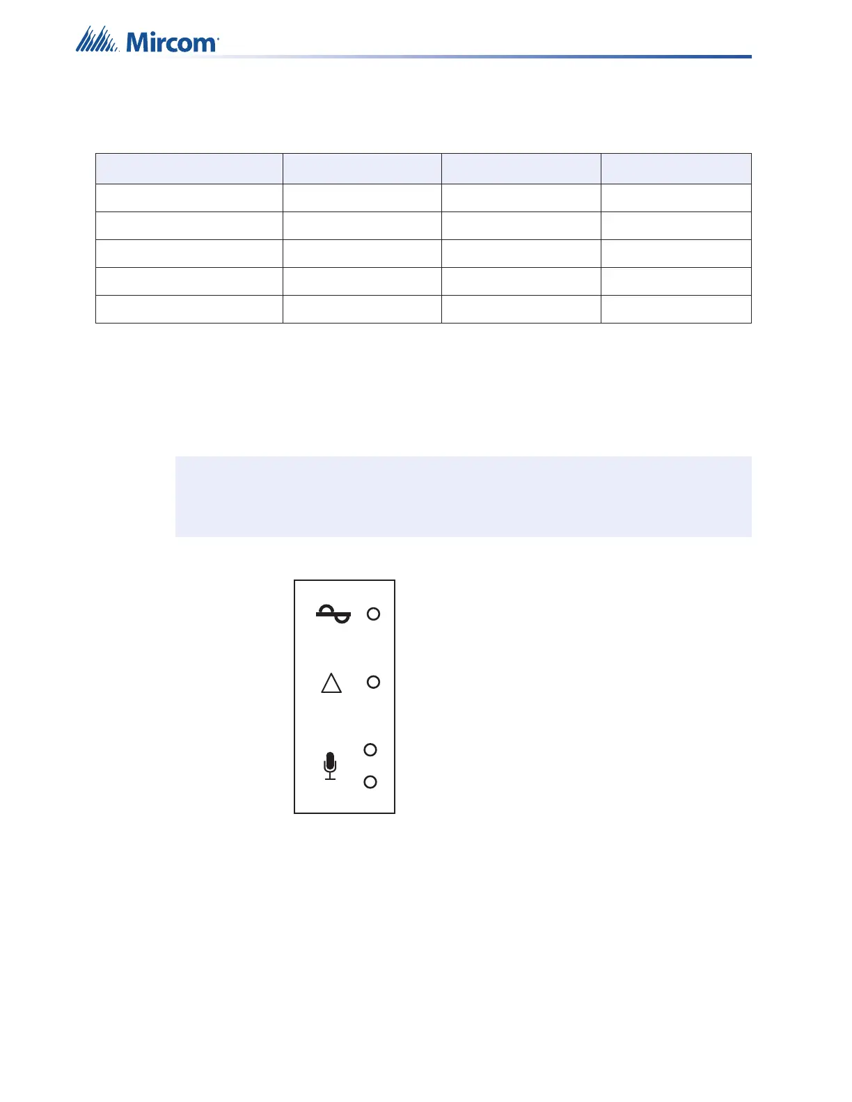
5.5 Remote Microphone Indicators
The QX-mini-RM remote microphone display panel has 4 LED indicators and 1 control (the
push-to-talk button on the microphone). This section describes the purposes of these
indicators.
Figure 59 The QX-mini-RM display panel LEDs
Table 16 Descriptions of QAD-30 amplifier module LEDs
LED Color Indication Action
Output 1 Active Green Status Steady
Output 2 Active Green Status Steady
Output 1 Trouble Yellow Status Steady
Output 2 Trouble Yellow Status Steady
Amplifier Trouble Yellow Trouble Steady
Note: RM not for use in Canada.
AC Power
Common Trouble
Ready to Page
System in Use
!

 Loading...


