62
Wiring
4.1 Wiring Tables
Mircom recommends using AWG#18 to AWG#12 shielded twisted pair (or triple) in each cable,
subject to Authority Having Jurisdiction.
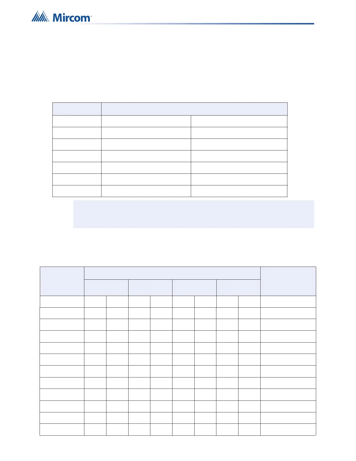
4.1.1 Wiring Tables for Inputs
Table 10 Wiring Table for Input Circuits (Relay Inputs and Synch Inputs)
Wire Gauge Maximum Wiring Run to Last Device (ELR)
(AWG) ft m
22 2990 910
20 4760 1450
18 7560 2300
16 12000 3600
14 19000 5800
12 30400 9200
Note: Maximum Loop Resistance Should Not Exceed 100 Ohms.
4.1.2 Wiring Tables for NAC Circuits
Table 11 Wiring Table for NAC Circuits
TOTAL
SIGNAL
LOAD
MAXIMUM WIRING RUN TO LAST DEVICE (ELR) MAX. LOOP
RESISTANCE
18AWG 16AWG 14AWG 12AWG
Amperes ftmftmftmftm Ohms
0.06 2350 716 3750 1143 6000 1829 9500 2895 30
0.12 1180 360 1850 567 3000 915 4720 1438 15
0.30 470 143 750 229 1200 366 1900 579 6
0.60 235 71 375 114 600 183 950 289 3
0.90 156 47 250 76 400 122 630 192 2
1.20 118 36 185 56 300 91 470 143 1.5
1.50 94 29 150 46 240 73 380 115 1.2
1.70 78 24 125 38 200 61 315 96 1.0
2.0 70 21 112 34 178 54 285 86 0.9
2.25 62 19 100 30 158 48 250 76 0.8
2.50 56 17 90 27 142 43 230 70 0.72

 Loading...


