126
12.0 Appendix B: Power Supply & Battery
Calculations
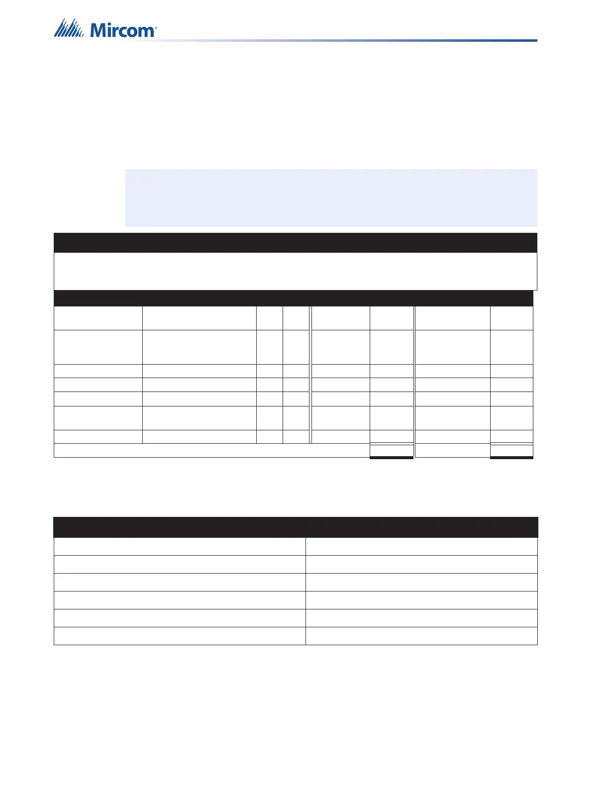
Use the form below to determine the required Secondary Power Supply (batteries) for each QX-MINI/
QX-MINI-BP and its accessories.
*For multiple current (range) rated products, the highest current ratings are to be used.
Total Speaker Current Requirement During Alarm (D)
Battery Calculations continued on next page...
Note: Secondary Power Supply (Battery) circuit is supervised, if software is configured
for batteries.
IMPORTANT NOTICE
The main AC branch circuit connection for Fire Alarm Control Unit must provide a dedicated continuous power without provision of any
disconnect devices. Use #12 AWG wire with 600-volt insulation and proper over-current circuit protection that complies with the local
codes. Refer to section 11.0 Appendix A: Specifications And Features on page 124 for specifications.
Power Requirements (All currents are in amperes)
Model Number Description Qty Standby
Total
Standby
Alarm
Total
Alarm
QX-mini / QX-mini-BP
Main Chassis Board +
Display Board / Booster
Board
1 X 0.215 / 0.210
=0.215 /
0.210
0.220 / 0.210
=0.220 /
0.210
QAD-30 30 Watt Amplifier X 0.031 = D =
QAS-2X8 Audio Zone Splitter X 0.023 = 0.091 =
QX-mini-RM Remote Microphone X 0.013 = 0.0161 =
QX-mini-LOC
Local Operating Console
RMIC + Display Board
X 0.023 = 0.040 =
QAZT-5302DS 24 Zone Controller X 0.010 = 0.015 =
Total currents (Add above currents) STANDBY (A) ALARM (B)
Total Wattage of Speakers Amplifier Current
Up to 5W 0.431
Up to 10W 0.703
Up to 15W 1.028
Up to 20W 1.311
Up to 25W 1.649
Up to 30W 2.025

 Loading...


