89
Indicators & Controls
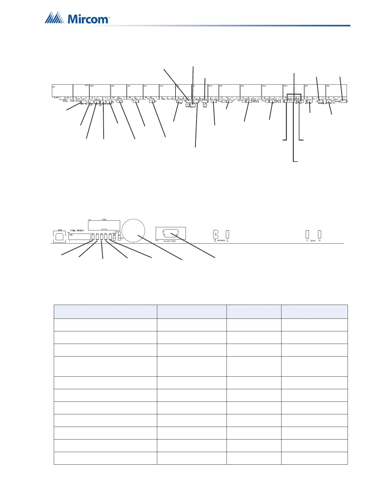
Figure 57 Locations of the QX-mini main board LEDs and buzzer
Table 15 Descriptions of QX-mini main board LEDs
LED Color Indication Action
Alarm (Relay) Active Red Alarm Steady
AC Trouble (Relay) Active Yellow Trouble Steady
Common Trouble (Relay) Active Yellow Trouble Steady
Activity on Remote Microphone
RS-485
Green Active Blinking
Activity on Inter-panel RS-485 Green Active Blinking
A TRB Yellow Trouble Steady
A RX Green Active Blinking
B TRB Yellow Trouble Steady
B RX Green Active Blinking
CPU TX Green Active Blinking
Master Mic Trouble Yellow Trouble Steady
Trouble
Buzzer
Power
CPU
FAIL
Battery
Trouble
Ground
Fault
Main Mic
Trouble
Remote Mic
Trouble
Relay 1
Trouble
Relay 2
Trouble
Relay 1
Active
Relay 2
Active
Alarm
AC
Trouble
Common
Trouble
RS485 OUT
Trouble
RS485 IN
Trouble
RS485 OUT
Receiving
CPU
Transmiting
RS485 IN
Receiving
Aux 24V
SLC
Synch
Input 1
Synch
Input 2
Synch
Output
NAC 1
ON
NAC 2
ON
NAC 1
Trouble
NAC 2
Trouble
For (Future
Use)
OUTPUT 1
OUTPUT 2
Synch Output
Trouble

 Loading...


