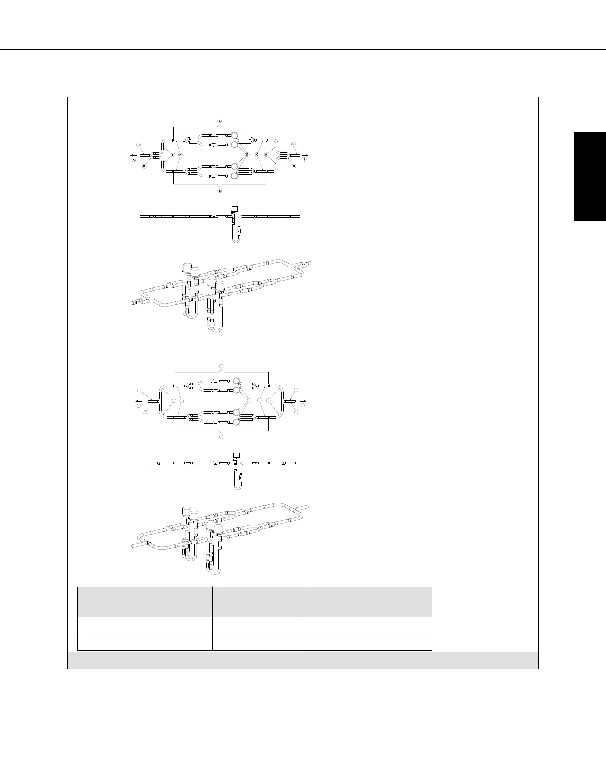
Figure 6-3 shows the installation 2 LEV Assemblies in parallel.
Piping configuration with Y-Distributors
Piping configuration with T-Joints
Ⓐ To AHU Heat exchanger (field
supply)
Ⓑ LEV Assembly
Ⓒ Brazing
Ⓓ LEV
Ⓔ To Outdoor unit
Ⓕ Refrigerant pipe size ø1/2”
(field supply)
Ⓖ Distributor (field supply)
Ⓗ Refrigerant pipe size (field
supply) based on outdoor unit
piping specification
LEV Assembly Model Capacity Code
Setting [Ton]
Design Capacity Range
[Btu/h]
LEV PAC-LV96AC-1 (x2) 12, 14, 16 120,000 - 192,000
LEV PAC-LV120AC-1 (x2) 18, 20 192,000 - 240,000
Fig. 6-3
PAC-AH001-1
25 © 2017 Mitsubishi Electric US, Inc.
ENGLISH
 Loading...