Signal Connection Circuit Signal Details
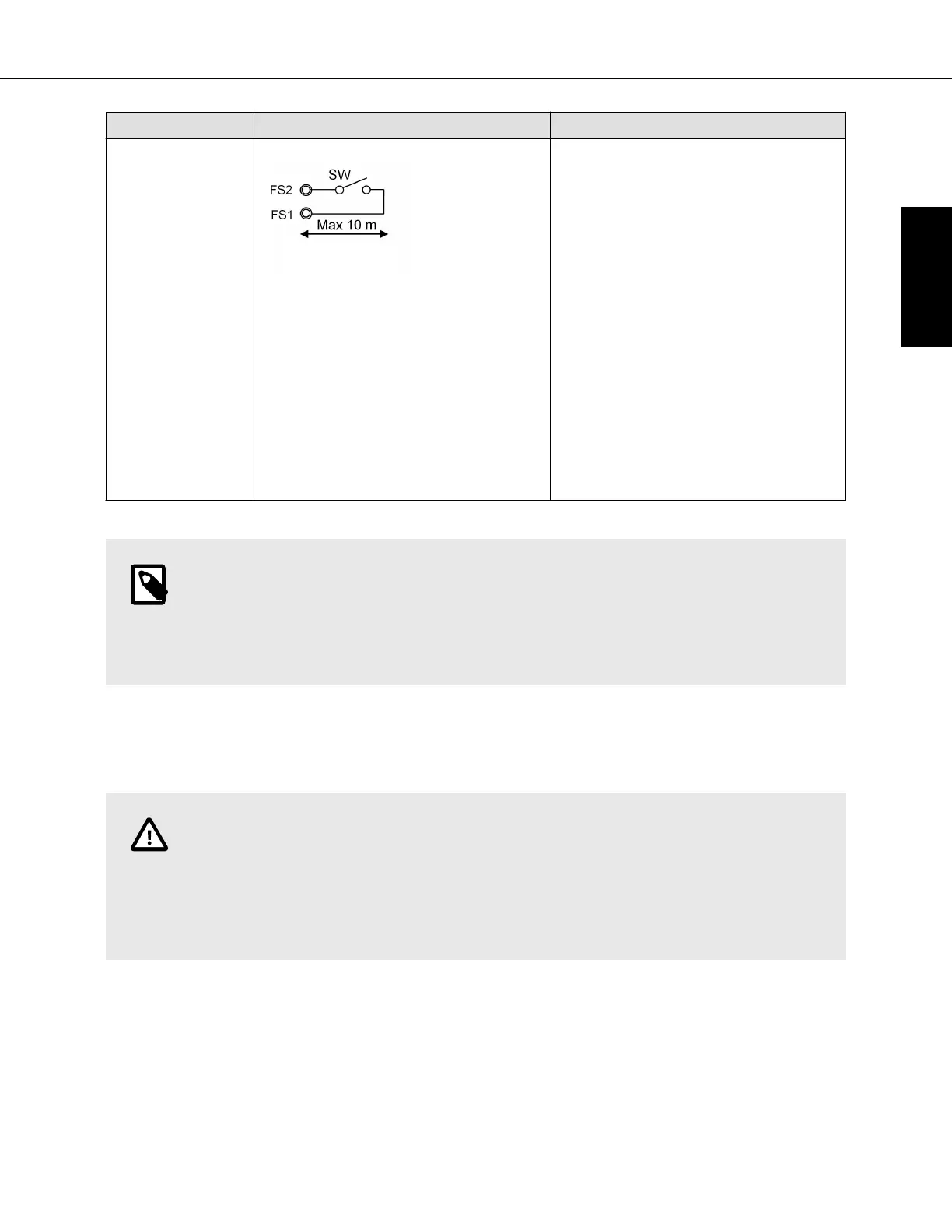
Float Switch
Input
Contact Input
Use a relay when wire
length exceeds 10 m
SW: Operation command (field
supply)
Minimum applicable load (switch) DC
5 V, 1mA
• The switch should be a normally
closed low voltage rated switch.
• The switch should be installed in a
location that it can sense a drain
blockage causing a rise in water
level. This resulting rise in level will
cause it to open.
• The switch location is to be
determined by the installing
contractor.
• When the switch opens, it will
cause the LEV to close, stopping
the cooling operation. The fan will
continue to run and a fault code will
be shown at the controller.
Correcting the problem and closing
the switch will be required before
normal operation can resume.
NOTE
After connecting each wire to the terminal, tighten each nut tightly through which the wire
runs.
Check that the bunch of wires do not come off even if they are pulled strongly.
7.5 External I/O specifications
CAUTION
1. Wiring should be covered by insulation tube with supplementary insulation.
2. Use relays or switches with IEC or equivalent standard.
3. The electric strength between accessible parts and control circuit should have 2750 V
or more.
PAC-AH001-1
41 © 2017 Mitsubishi Electric US, Inc.
ENGLISH
 Loading...