8.5 Electric Heater Control
NOTE
• Electric heat will only operate when DIP SW are set for AHU controller to operate in
Return Air Control.
• If DIP SW are set for AHU controller to operate in Return Air Control, Damper Signal
Output can be used to control 2nd stage electric heat (EH2).
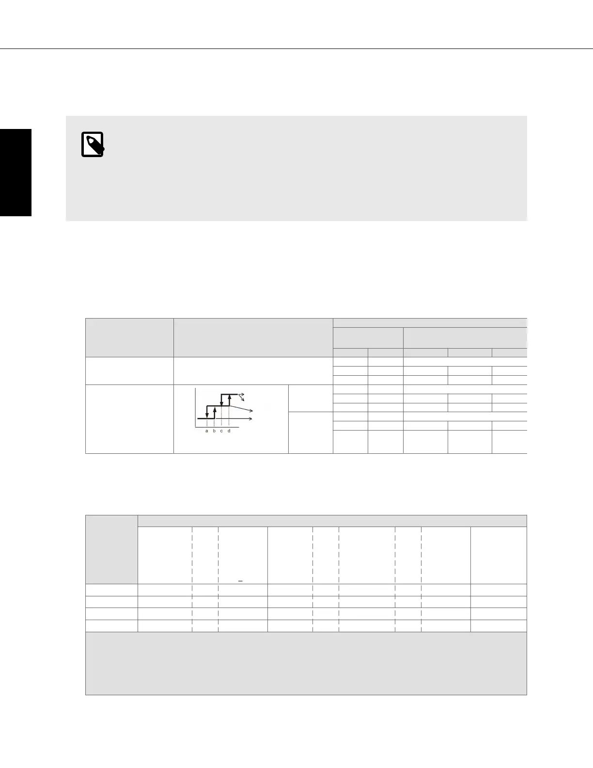
• Control specifications and DIP S/W setting
– Table 1 shows the function settings for the field-installed heater. Select the desired pattern in the table
below, and set the DIP SW on the outdoor and indoor units as shown in Table 1.
Table 1. [DIP S/W]
8.5 Electric Heater Control
NOTE
• Electric heat will only operate when DIP SW are set for AHU controller to operate in Return Air Control.
• If DIP SW are set for AHU controller to operate in Return Air Control, Damper Signal Output can be used to control 2nd stage electric heat (EH2).
• Control specifications and DIP S/W setting
• Table 1 shows the function settings the field-installed heater. Select the desired pattern in the table below, and set the DIP SW on the outdoor and indoor units as shown in Table 1.
Table 1. [DIP S/W]
Outdoor unit setting Condition of outdoor unit
PAC-AH001-1
DIP SW
(AHU controller)
a
Heater Control
SW3-2 SW3-4 Mode Defrost Error
DIP S/W OFF In the case of:
TKMU/YKMU: SW4: 932 OFF
TLMU/YLMU: SW4: 932 OFF
N / A
OFF - Heater not Available
ON OFF Heater Available OFF OFF
ON ON Heater Available ON ON
b
DIP S/W ON In the case of:
TKMU/YKMU:
SW4: 932 ON
TLMU/YLMU:
SW4: 932 ON
Parameters a/b/c/d are set by
maintenance tool.
Normal drive
Defrost drive
H/P drive
H/P drive
Condition of O/U
Outdoor temp.
Normal Drive
OFF - Heater not Available
ON OFF Heater Available OFF OFF
ON ON Heater Available ON
Defrost drive
H/P drive
H/P stop
OFF - Heater not Available
ON OFF Heater Available OFF OFF
ON ON Heater Available ON
a
Default settings: SW3-2 OFF, SW3-4 OF
b
Heater will not operate during all error modes. Heater will only operate during a communication error between indoor unit and outdoor unit.
c
Heater will not operate during all error modes. Heater will only operate during a communication error between indoor unit and outdoor unit.
d
Heater will not operate during all error modes. Heater will only operate during a communication error between indoor unit and outdoor unit.
• Table 2 shows how the field-installed heater is controlled
1
ON
b
ON
b
– Table 2 shows how the field-installed heater is controlled.
Table 2. [Heater Control Table]
Table 2
Table 2. [Heater Control Table]
1
Mode Change
Condition
(T
O
-T
RA
)
> 2.7 °F[1.5 °C]
AND
T
RA
has not
increased by
0.9 °F [0.5°C]
in X min
EH1 ON for
> 5 min
AND
(T
O
-T
RA
)
> 2.7 °F [1.5 °C]
AND
T
RA
has not
increased by
0.9 °F [0.5°C]
in 5 min
(T
O
-T
RA
)
< 0.9 °F [0.5°C]
EH1 ON ● AND ●
EH2 ON ● AND ● AND ●
EH1 OFF ●
EH2 OFF ●
KEY
• EH1: Electric Heater 1 (CN24)
• EH2: Electric Heater 2 (CN27)
• T
O
: Set point temperature
• T
RA
: Return Air temperature
• X: Time delay (Selectable. Default is 20 min. Selectable to 10, 15, or 25 min)
PAC-AH001-1
Specifications are subject to change without notice. 48
ENGLISH
 Loading...