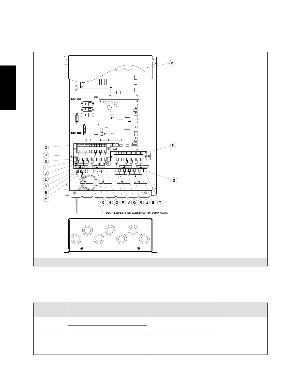
Connecting wiring
V U
L
M
N O
H
I
J
K
P Q R S T
COIL THE WIRES TO THE CABLE STRAP FOR STRAIN RELIEF.
A
F
G
B
D
E
C
Ⓐ Cover
Ⓑ Power Supply Terminal Block
(208, 230 VAC)
Ⓒ M-Net Terminal Block
Ⓓ Terminal Block TB-A
Ⓔ Terminal Block TB-B
Ⓕ Terminal Block TB-C
Ⓖ Terminal Block TB-D
Ⓘ Damper Signal Output (D1,
D2)
Ⓙ MA Controller (1, 2)
Ⓚ Analog Input (B1, B2)
Ⓛ Operation Signal Output
(Ocom, OE, OH, OC, OD)
Ⓜ Heater Signal Output (H1,
H2)
Ⓝ Remote Signal Input (A1, A2)
Ⓞ Error Signal Input (E1, E2)
Ⓟ Float Switch Input (FS1, FS2)
Ⓠ Thermistor, Outlet Air (TH1,
TH2)
Ⓡ Thermistor, Gas Pipe (TH3,
TH4)
Ⓢ Thermistor, Liquid Pipe (TH5,
TH6)
Ⓣ Thermistor, Inlet Air (TH7,
TH8)
Ⓤ LEV 1
Ⓥ LEV 2
Fig 7.0.1
Wind the wire around the cable strap once to prevent loose wires as shown in the figure.
Transmission cable specifications
Transmission cables ME Remote controller
cables
MA Remote
controller cables
Type of
cable
Shielding wire (2-core)
Sheathed 2-core cable (unshielded) CVV
CVVS, CPEVS or MVVS
Cable
diameter
AWG16 [1.25 mm
2
] shielding
wire (2-core) CVVS, CPEVS or
MVVS
AWG 20 -16 (0.5 - 1.25
mm
2
)
a
AWG 22-16 (0.3 -
1.25 mm
2
)
a
PAC-AH001-1
Specifications are subject to change without notice. 30
ENGLISH
 Loading...