7.2.1 Connection to Outdoor Unit
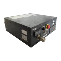
• Connect the “M1”, “M2” and “S” on AHU controller terminal block to the TB3 on the outdoor unit as shown
in Figure 7.2.1. (Non-polarized 2-wire) The “S” on AHU controller TB5 is a shielding wire connection.
For specifications about the connecting cables, refer to the outdoor unit installation manual.
Ⓐ Terminal block for AHU
controller/ indoor transmission
cable
Ⓑ Terminal block for outdoor
transmission cable
Fig 7.2.1
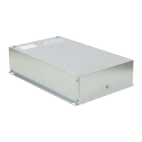
7.2.2 Connection for Operation with Mitsubishi Electric Controller
• Connect a Mitsubishi MA controller:
To connect an MA controller, connect the 2 wires of the MA controller to positions “1” and “2” of the
terminal labeled “MA Control.” on the AHU controller terminal block (Non-polarized 2-wire). Figure 7.2.2.0
shows an AHU controller system controlled with MA controllers.
TB5TB5
SM1M2 SM1M2
TB3
M1M2 21 21
AA
B
CC
Ⓐ Terminal block for AHU
controller/ indoor transmission
cable
Ⓑ Terminal block for outdoor
transmission cable
Ⓒ Remote controller
Fig 7.2.2.0
• Connect a Mitsubishi ME controller (or system controller):
To connect an ME controller (or system controller), connect the 2 wires of the controller to the positions
labeled “M1” and “M2” of the terminal labeled “M-NET” on the AHU controller terminal block (Non-
polarized 2-wire). Figure 7.2.2.1 shows an AHU controller system controlled with ME controllers.
PAC-AH001-1
33 © 2017 Mitsubishi Electric US, Inc.
ENGLISH
 Loading...